Table of Contents
Easy Smart Switch User Guide
About This Guide
This Configuration Guide provides information for configuring the Easy Smart Switch via the web interface. Read this guide carefully before operation.
You can also configure the switch using the Easy Smart Configuration Utility. For more information, refer to the Easy Smart Configuration Utility User Guide. Go to the website https://www.tp-link.com/support, search the model number of your switch, and you can find this guide on the product Support web page.
Intended Readers
This Guide is intended for network managers familiar with IT concepts and network terminologies.
Conventions
When using this guide, notice that features available in Easy Smart Switch may vary by model and software version. The availability of Easy Smart Switch may also vary by region or ISP. All images, steps, and descriptions in this guide are only examples and may not reflect your actual experience. Throughout the guide, we will take TL-SG1016PE as the switch to be configured for example.
Some models featured in this guide may be unavailable in your country or region. For local sales information, visit https://www.tp-link.com.
The information in this document is subject to change without notice. Every effort has been made in the preparation of this document to ensure accuracy of the contents, but all statements, information and recommendations in this document do not constitute the warranty of any kind, express or implied. Users must take full responsibility for their application of any products.
In this Guide, the following conventions are used:
PoE budget calculations are based on laboratory testing. Actual PoE power budget is not guaranteed and will vary as a result of client limitations and environmental factors.
The symbol stands for Note. Notes contain suggestions or references that help you make better use of your device.
Menu Name > Submenu Name > Tab page indicates the menu structure. SYSTEM > System Info > System Summary means the System Summary page under the System Info menu option that is located under the SYSTEM menu.
Bold font indicates a button, toolbar icon, menu or menu item.
More Information
● The latest software and documentations can be found at Download Center at https://www.tp-link.com/support.
● The Installation Guide (IG) can be found where you find this guide or inside the package of the switch.
● The authentication information can be found where you find this guide.
● Specifications can be found on the product page at https://www.tp-link.com.
● To ask questions, find answers, and communicate with TP-Link users or engineers, please visit https://community.tp-link.com to join TP-Link Community.
● Our Technical Support contact information can be found at the Contact Technical Support page at https://www.tp-link.com/support.
Chapter 1 Introduction
1.1 Product Overview
Easy Smart Switch is an ideal upgrade from Unmanaged Switch, designed for Small Office and Home Office networks. The switch supports the following features:
● Traffic monitoring: Port mirroring, loop prevention and cable test enable the administrator to monitor traffic of the network effectively.
● VLAN: MTU VLAN, Port based VLAN and 802.1Q VLAN can restrict broadcast domain, enhance network security and help manage devices easily.
● QoS: Port based QoS, 802.1P based QoS and DSCP/802.1P based QoS optimize traffic on your business network, and keep latency-sensitive traffic moving smoothly. Bandwidth control helps distribute and utilize network bandwidth reasonably. Storm control helps avoid network broadcast storm.
● PoE: PoE (Power over Ethernet) is a remote power supply function. With this function, the switch can supply power to the connected devices over twisted-pair cables.
 Note:
Note:
The PoE Config is only available on TL-SG1016PE, TL-SG1218MPE and TL-SG1428PE. For TL-SG108PE, TL-SG105PE and TL-SG1210MPE, this feature is not supported.
1.2 Logging Into the Switch
To configure your switch through a web browser on your PC, follow these steps:
1) Connect your switch to the network and connect your PC to the switch.
2) Find out the IP address of the switch.
● By default, the switch receives an IP address from a DHCP server (or a router that functions as a DHCP server) in your network. You can find out this IP address on the DHCP server.
● If the switch cannot receive an IP address from a DHCP server, it uses the static IP address of 192.168.0.1, with a subnet mask of 255.255.255.0.
3) Configure IP address on your PC to make sure the switch and PC are in the same subnet.
● If the switch uses an IP address assigned by a DHCP server, set your PC to obtain an IP address automatically from the DHCP server.
● If the switch uses the static IP address of 192.168.0.1, configure your PC’s IP address as 192.168.0.x (”x” ranges from 2 to 254), and subnet mask as 255.255.255.0.
4) Launch a web browser on your PC. The supported web browsers include, but are not limited to, the following types:
● IE 8.0, 9.0, 10.0, 11.0
● Firefox 26.0, 27.0
● Chrome 32.0, 33.0
5) In the address bar of the web browser, enter the IP address of the switch. Here we suppose the switch uses the static IP address 192.168.0.1.

6) Enter the username and password in the pop-up login window. Before proceeding with further configuration, you need to set up username and password by following the prompts on the page (if prompted to log in before setting username and password, use admin for both the username and password).
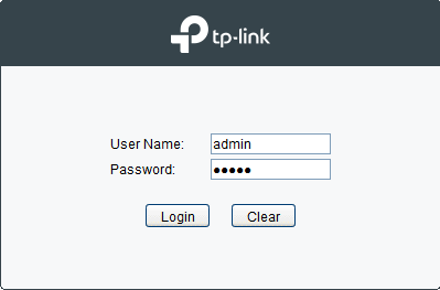
Note:
The first time you log in, change the password to better protect your network and devices.
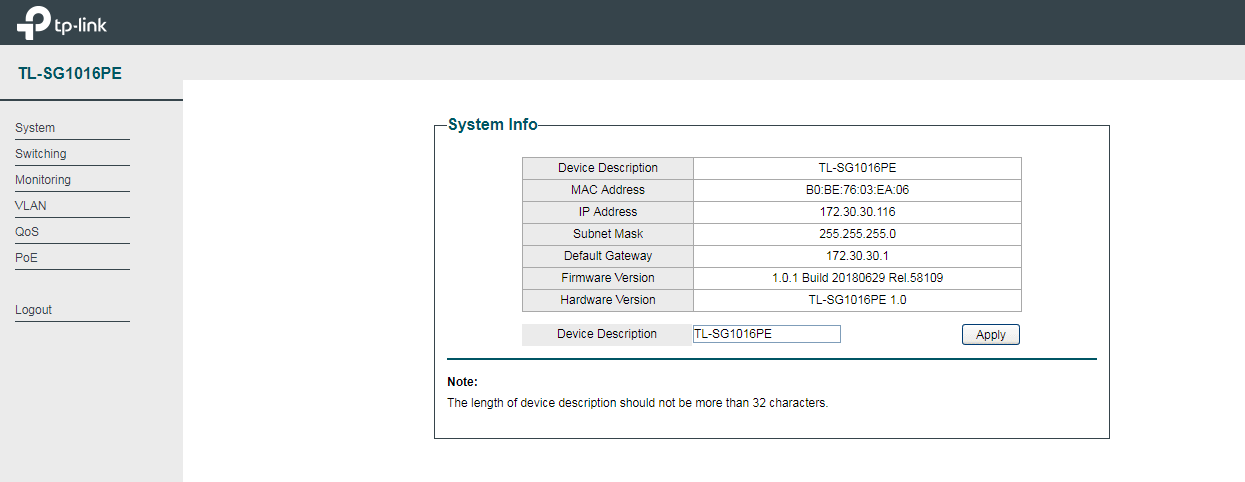
7) The typical web interface displays below. You can view the running status of the switch and configure the switch on this interface.
Chapter 2 Managing System
2.1 System
2.1.1 Overview
In System module, you can view the system information and configure the system parameters and features of the switch.
2.1.2 Supported Features
System Info
The System Info is mainly used to view the system information and configure the device description.
IP Setting
Each device in the network possesses a unique IP address. You can access the switch using IP address of the switch. You can set IP address of the switch manually or using DHCP.
User Account Management
User Account Management is mainly used to modify the administrator’s username and password in order to refuse illegal users.
Backup and Restore
Backup and Restore is used to download the current configuration and save it as a file to your computer, and upload a backup configuration file to restore your switch to the previous configuration.
System Reboot
System Reboot is used to reboot the switch.
System Reset
System Reset is used to reset the switch to the factory default setting. All the settings will be cleared after the switch is reset.
Firmware Upgrade
To upgrade the firmware is to get more functions and better performance. Go to the website https://www.tp-link.com to download the updated firmware.
2.2 Configuring System Info
With system information configuration, you can:
● View the system information
● Specify the device description
2.2.1 Viewing the System Information
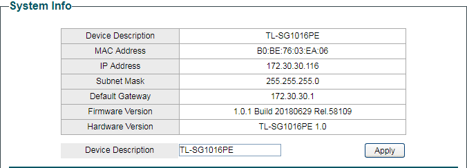
Choose the menu System > System Info to load the following page. You can view the basic system information of the switch.
2.2.2 Specifying the Device Description
Choose the menu System > System Info to load the following page. Specify a new device description for the switch, and click Apply.
2.3 Configuring IP
You can configure the system IP address in the following two ways:
● Configure the System IP Address Using DHCP
● Configure the System IP Address Manually
Configuring the System IP Address Using DHCP
Choose the menu System > IP Setting to load the following page.
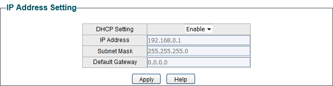
Follow these steps to configure the system IP address using DHCP:
1) Select DHCP setting as Enable from the drop-down list .
2) Click Apply. The switch will obtain IP settings from the DHCP server.
Configuring the System IP Address Manually
Choose the menu System > IP Setting to load the following page.
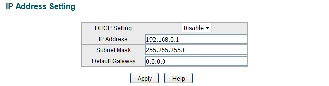
Follow these steps to configure the system IP address manually:
1) Select DHCP setting as Disable from the drop-down list.
2) Specify the IP address, subnet mask and default gateway.
| IP Address | Specify the system IP of the switch. You can use this IP address to access the switch. |
|---|---|
| Subnet Mask | Specify the subnet mask of the switch. |
| Default Gateway | Specify the default gateway of the switch. |
3) Click Apply.
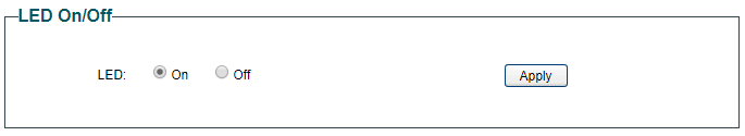
2.4 Configuring LED (Only for Certain Devices)
Note:
LED configuration is only available on certain devices. To check whether your device supports this feature, refer to the actual web interface.
With this function, you can turn on or turn off the LED with one click.
Choose the menu System > LED On/Off to load the following page. Choose the LED status and click Apply.
2.5 Configuring User Account
With user account management, you can modify the administrator’s username and password in order to refuse illegal users.
Choose the menu System > User Account to load the following page.
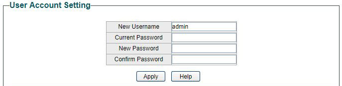
Follow these steps to configure the user account:
1) Specify the new username, enter the current password, specify a new password and confirm the new password.
| New Username | Create a user name for login. Requirement for the user name varies among different devices. If your user name fails to meet the requirement, check the prompt information. |
|---|---|
| Current Password | Enter the current password of the switch. Before proceeding with further configuration, you need to set up username and password. If prompted to log in before setting username and password, use admin for both the username and password. |
| New Password | Specify a new password for login. Requirement for the password varies among different devices. If your password fails to meet the requirement, check the prompt information. |
| Confirm Password | Retype the new password. |
2) Click Apply.
2.6 Backing up and Restoring the Switch
2.6.1 Saving the Current Configuration
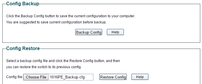
Choose the menu System > System Tools > Backup and Restore to load the following page. In the Config Backup section, click Backup Config to save the configuration file to your PC.

Note:
It will take several minutes to save the configuration file. Wait without any operation.
2.6.2 Restoring to the Previous Configuration
Choose the menu System > System Tools > Backup and Restore to load the following page.
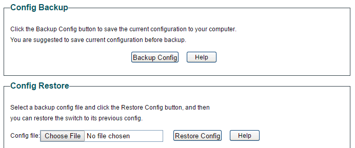
Follow these steps to restore the switch to the previous configuration:
1) In the Config Restore section, click Choose File to load the following page. Specify the configuration file path and select the configuration file.
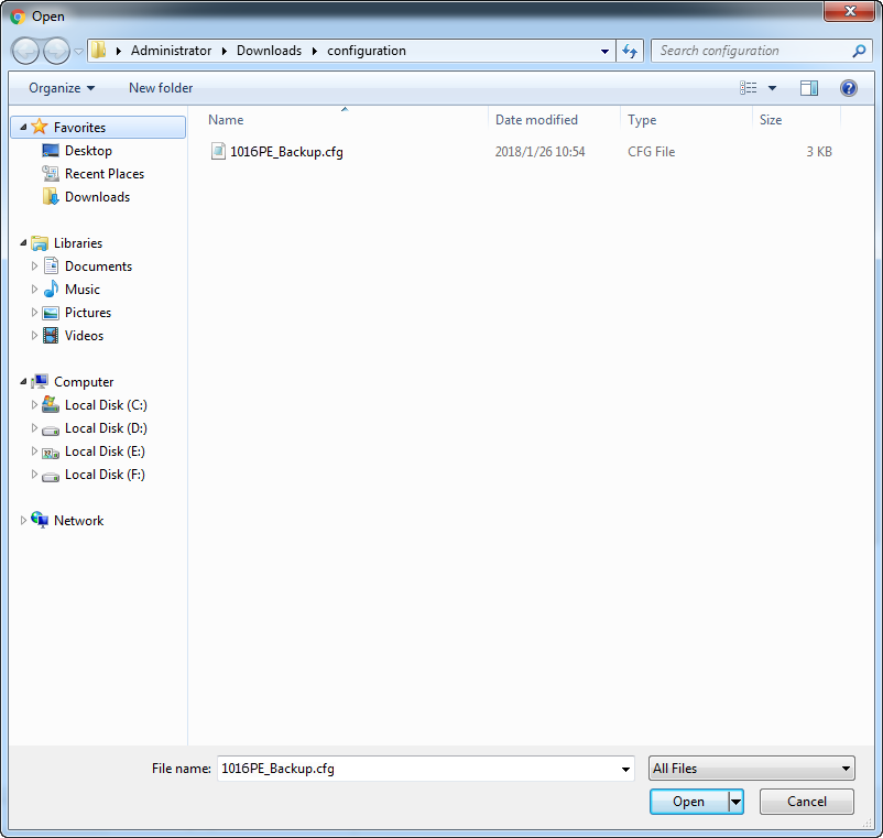
2) Click Open and the following page will be displayed. In the Config Restore section, click Restore Config to restore the switch to the previous configuration. It will take effect after the switch automatically reboots.
Note:
● It will take several minutes to restore the configuration. Wait without any operation.
● To avoid any damage, do not power down the switch while being restored.
● After being restored, the current configuration of the switch will be lost.
2.7 Rebooting the Switch
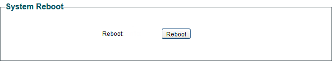
Choose the menu System > System Tools > System Reboot to load the following page. Click Reboot.
Note:
● It will take several minutes to reboot the switch. Wait without any operation while the switch reboots.
● To avoid any damage, do not power down the switch while the switch reboots.
2.8 Resetting the Switch
Choose the menu System > System Tools > System Reset to load the following page.

Follow these steps to reset the switch.
1) Click Reset, and the following page will pop up.
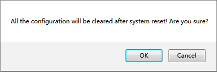
2) Click OK to reset the switch.
Note:
● After the switch is reset, it will reboot automatically.
● It will take several minutes to reboot the switch. Wait without any operation while the switch reboots.
● To avoid any damage, do not power down the switch during the reset.
● After the switch is reset, all the settings will be restored to the default.
2.9 Upgrading the Firmware
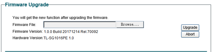
Choose the menu System > System Tools > Firmware Upgrade to load the following page.
Follow these steps to upgrade the firmware:
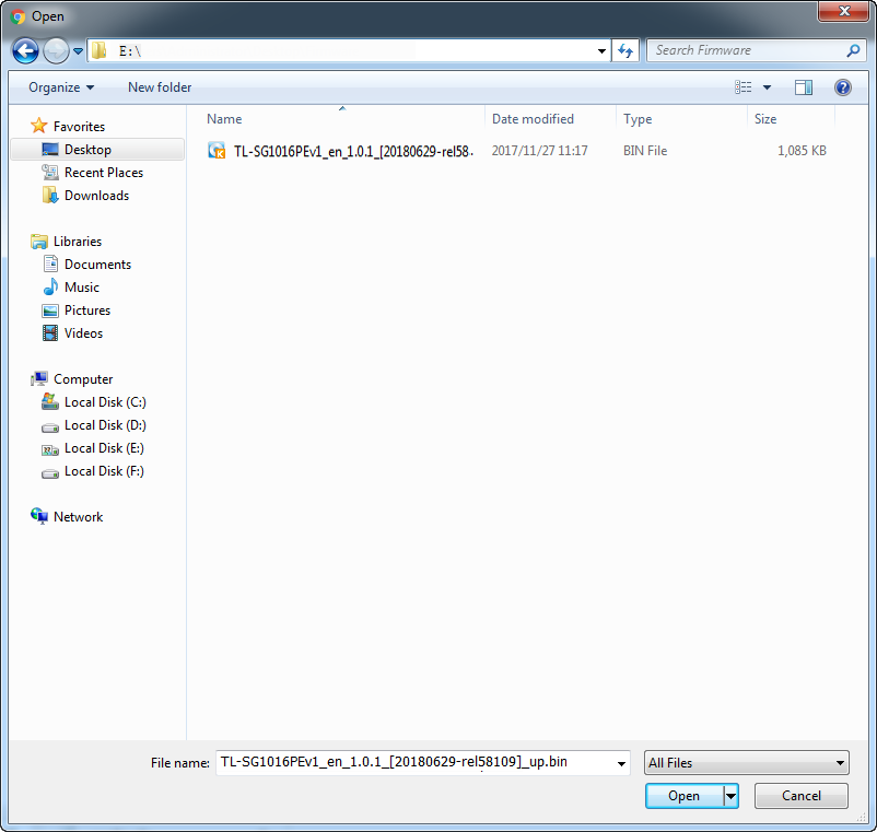
1) Click Choose File to load the following page. Specify the firmware file path and select the firmware to upgrade.
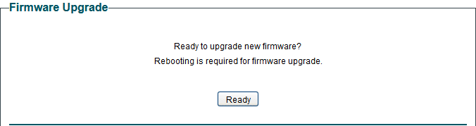
2) Click Open and the following page will be displayed. Click Upgrade.
Note:
● It will take several minutes to upgrade the firmware. Wait without any operation.
● Select the proper software version matching with the hardware to upgrade.
● To avoid damage, do not power down the switch while upgrading the firmware.
● It is recommended to backup the configuration before upgrading.
2.10 Appendix: Default Parameters
Default settings of System Info are listed in the following table.
| Parameter | Default Setting |
|---|---|
| Device Description | The model name of the switch. |
Default settings of IP Setting are listed in the following table.
| Parameter | Default Setting |
|---|---|
| DHCP Setting | Enable |
| IP Address | 192.168.0.1 |
| Subnet Mask | 255.255.255.0 |
| Default Gateway | 0.0.0.0 |
Default settings of User Account are listed in the following table.
| Parameter | Default Setting |
|---|---|
| New Username | admin |
Chapter 3 Switching
3.1 Switching
3.1.1 Overview
With the switching feature, you can configure port setting, IGMP Snooping and LAG.
3.1.2 Supported Features
The switch supports the following features about switching:
Port Setting
You can configure port status, speed, duplex mode and flow control for ports.
IGMP Snooping
In a point-to-multipoint network, packets can be sent in three ways: unicast, broadcast and multicast. With unicast, many copies of the same information will be sent to all the receivers, occupying a large bandwidth.
With broadcast, information will be sent to all users in the network no matter they need it or not, wasting network resources and impacting information security.
Multicast, however, solves all the problems caused by unicast and broadcast. With multicast, the source only needs to send one piece of information, and all and only the users who need the information will receive copies of the information. In a point‑to‑multipoint network, multicast technology not only transmits data with high efficiency, but also saves a large bandwidth and reduces network load.
When IGMP Snooping is disabled on the switch, multicast packets will be broadcast in the Layer 2 network; when IGMP Snooping is enabled on the switch, multicast data from a known multicast group will be transmitted to the designated receivers instead of being broadcast in the Layer2 network. The following figure shows how IGMP snooping works.

LAG
With LAG (Link Aggregation Group) function, you can aggregate multiple physical ports into a logical interface to increase link bandwidth and enhance the connection reliability.
3.2 Configuring Ports
Choose the menu Switching > Port Setting to load the following page.
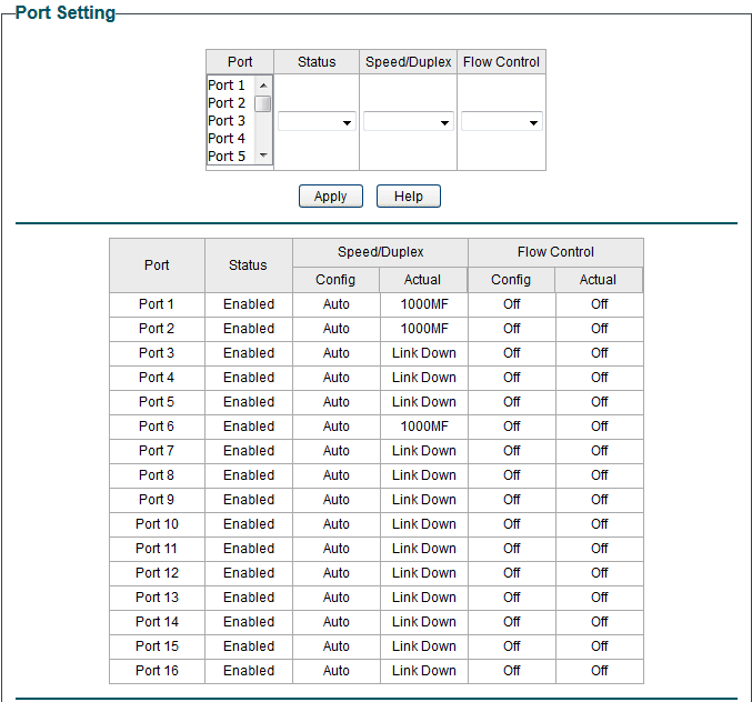
Follow these steps to configure the port parameters.
1) Select the desired ports and set basic parameters for the ports.
| Status | Enable or disable the port. With this option enabled, the port forwards packets normally. Otherwise, the port cannot work. By default, it is enabled. |
|---|---|
| Speed/Duplex | Select the appropriate speed and duplex mode for the port. When Auto is selected, the port automatically negotiates speed mode with the connected device. It is recommended to select Auto if both ends of the link support auto-negotiation. |
| Flow Control | Select On or Off to enable or disable the Flow Control feature. When Flow Control is enabled, when the switch gets overloaded, it will send a PAUSE frame to notify the peer device to stop sending data for a specific period of time, thus avoiding the packet loss caused by congestion. |
2) Click Apply.
Note:
● It is recommended to set the ports on both ends of a link with the same speed and duplex mode.
● Keep the port that is connected to the management device enabled, or you cannot access the switch.
● The parameters of the port members in a LAG should be set as the same.
3.3 Configuring IGMP Snooping
Choose the menu Switching > IGMP Snooping to load the following page.
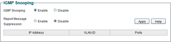
Follow these steps to configure IGMP Snooping.
1. Enable IGMP Snooping. Enable or disable report message suppression according to your needs. Click Apply.
|
IGMP Snooping |
Enable or disable IGMP Snooping globally. |
|---|---|
|
Report Message Suppression |
Enable or disable Report Message Suppression globally. When enabled, the switch will only forward the first IGMP report message for each multicast group to the IGMP querier during one query interval, and suppress subsequent IGMP report messages for the same multicast group. This feature prevents duplicate report messages from being sent to the IGMP querier. |
2. In the table below, you can view the current IGMP group information.
|
IP Address |
Displays the IP address of the multicast group. |
|---|---|
|
VLAN ID |
Displays the VLAN ID of the multicast group. All port members of a multicast group should be included in the same VLAN. |
|
Ports |
Displays the forwarding port list of the multicast group. |
3.4 Configuring LAG
Choose the menu Switching > LAG to load the following page.
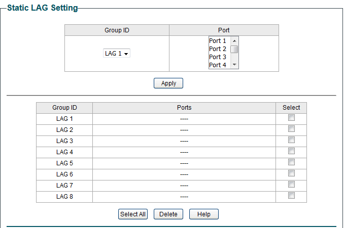

Follow these steps to configure LAG:
1) Select the desired LAG group from the drop-down list.
2) Click the ports to add to the LAG group. Click Apply.
3) In the table below, you can verify the LAG configuration result. You can select the LAG and click Delete to delete ports from the LAG group.
|
Group ID |
Displays the ID of the LAG group. |
|---|---|
|
Ports |
Displays the LAG member ports. |
Note:
● It is recommended to configure the LAG function before configuring the other functions for the member ports.
● Ensure that devices on both ends of the aggregation link use the same number of physical ports with the same speed and duplex mode, flow control setting and QoS setting.
● Mirroring and mirrored ports cannot be added to an LAG group.
● The maximum of LAG groups varies among different devices. To check the maximum of LAG groups, refer to the actual web interface.
● Each LAG group has 2 port members at least and 4 port members at most.
3.5 Configuration Examples
3.5.1 Example for Configuring IGMP Snooping
Network Requirements
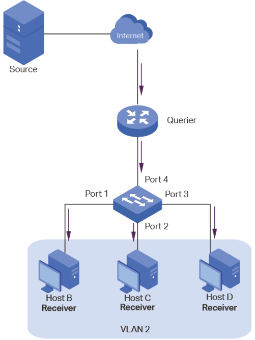
Host B, Host C and Host D are in the same VLAN of the switch. All of them want to receive multicast streams sent to the same multicast group.
As shown in the following topology, Host B, Host C and Host D are connected to port 1, port 2 and port 3 respectively. Port 4 is the router port connected to the multicast querier.
Configuration Scheme
■ Configure 802.1Q VLAN. Add the three member ports and the router port to the same VLAN.
■ Enable IGMP Snooping.
Demonstrated with TL-SG1016PE, the following section provides configuration steps.
Configuration Steps
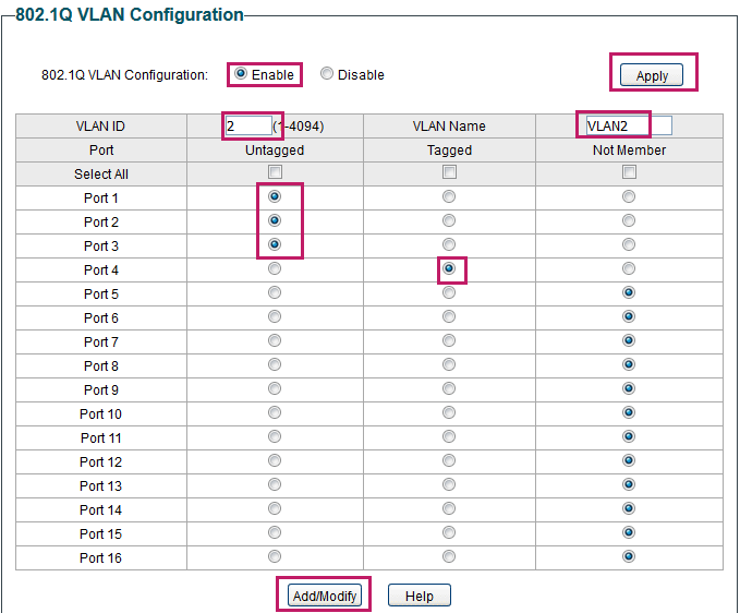
1) Choose the menu VLAN > 802.1Q VLAN to load the following page. Select the 802.1Q VLAN Configuration as Enable. Click Apply. Specify the VLAN ID as 2. Specify the VLAN name as VLAN2. Select port 1, port 2, port 3 as untagged ports. Select port 4 as a tagged port. Click Add/Modify.
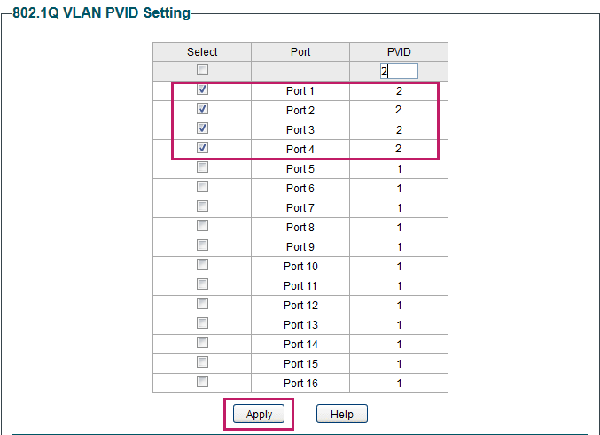
2) Choose the menu VLAN > 802.1Q PVID Setting to load the following page. Select port 1, port 2, port 3 and port 4, and specify the PVID as 2 for the ports. Click Apply.
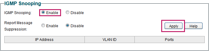
3) Choose the menu Switching > IGMP Snooping to load the following page. Enable IGMP snooping. Click Apply.
3.5.2 Example for Configuring LAG
Network Requirements
As shown below, hosts and servers are connected to Switch A and Switch B, and heavy traffic is transmitted between the two switches. To achieve high speed and reliability of data transmission, you can bundle multiple physical ports into one logical interface. In this case, we bundle port 1, port 2 and port 3 of both switches into one logical interface.
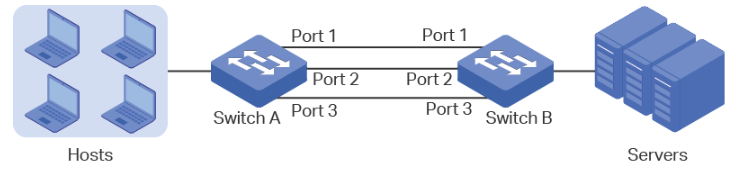
Demonstrated with TL-SG1016PE, the following section provides configuration steps. The configuration steps are similar for both switches, here we take Switch A for example.
Configuration Steps
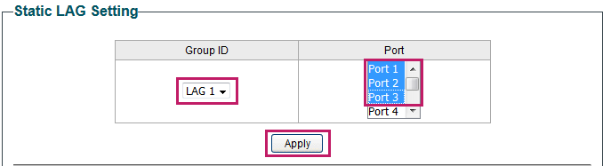
Choose the menu Switching > LAG to load the following page. Add Port 1, Port 2 and Port 3 to LAG 1. Click Apply.
3.6 Appendix: Default Parameters
Default settings of Port are listed in the following table.
|
Parameter |
Default Setting |
|
Status |
Enabled |
|
Speed/Duplex |
Auto |
|
Flow Control |
Off |
Default settings of IGMP Snooping are listed in the following table.
|
Parameter |
Default Setting |
|
IGMP Snooping |
Enable |
|
Report Message Suppression |
Disable |
Default settings of LAG are listed in the following table.
|
Parameter |
Default Setting |
|
Group ID |
LAG 1 |
Chapter 4 Monitoring
4.1 Monitoring
4.1.1 Overview
With the monitoring feature, you can monitor the traffic on the switch.
4.1.2 Supported Features
Port Statistics
Port Statistics is used to display the information of each port, which facilitates you to monitor the traffic and locate faults promptly.
Port Mirror
Port Mirror is used to monitor network traffic by forwarding copies of incoming and outgoing packets from one or multiple ports (mirrored ports) to a specified port (mirroring port). Generally, the mirroring port is connected to a data diagnosis device, which is used to analyze the mirrored packets for monitoring and troubleshooting the network.
Cable Test
This switch provides cable test to diagnose the connection status of the cable connected to the switch and the distance to the problem location, which facilitates you to locate and diagnose the trouble spot of the network.
Loop Prevention
With loop prevention feature enabled, the switch can detect loops using loop detection packets. When a loop is detected, the switch will block the corresponding port automatically.
4.2 Viewing Port Statistics
Choose the menu Monitoring > Port Statistics to load the following page.

You can view the statistics of each port. You can click Clear to clear the data, also you can click Refresh to refresh the data.
|
Port |
Displays the port number of the switch. |
|
Status |
Displays whether the port is enabled or disabled. |
|
Link Status |
Displays the link state of the port. |
|
TxGoodPkt |
Displays the number of packets transmitted on the port. Error packets are not counted in. |
|
TxBadPkt |
Displays the number of error packets transmitted on the port. |
|
RxGoodPkt |
Displays the number of packets received on the port. Error packets are not counted in. |
|
RxBadPkt |
Displays the number of error packets received on the port. |
Note:
● The frames with more than 1518 bytes, less than 64 bytes or with bad FCS (Frame Check Sequence) are recorded as BadPkts.
● Because of the supporting feature of jumbo frame, the frames with more than 1518 bytes and less than 10000 bytes will be recorded as GoodPkts and BadPkts at the same time, and can be forwarded normally.
4.3 Configuring Port Mirror
Choose the menu Monitoring > Port Mirror to load the following page.
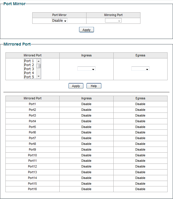
Follow these steps to configure port mirror:
1) Enable the port mirror feature globally. Specify a mirroring port. Click Apply.
|
Port Mirror |
Enable or disable the port mirror feature globally. |
|---|---|
|
Mirroring Port |
Select a port as the mirroring port. Traffic passing through the mirrored ports will be mirrored to the mirroring port. |
2) Select one or more mirrored ports, enable or disable the ingress packets and egress packets to be mirrored for the ports. Click Apply.
|
Mirrored Port |
Select one or more ports as mirrored ports. Traffic passing through the mirrored ports will be mirrored to the mirroring port. |
|---|---|
|
Ingress |
For each port, select whether the ingress packets are mirrored. With this option enabled, the packets received by the port will be copied to the mirroring port. With this option disabled, the packets received by the port will not be copied to the mirroring port. |
|
Egress |
For each port, select whether the egress packets are mirrored. With this option enabled, the packets sent by the port will be copied to the mirroring port. With this option disabled, the packets sent by the port will not be copied to the mirroring port. |
3) In the table below, you can verify the configuration result for port mirroring.
Note:
The LAG member ports cannot be set as a mirroring port or mirrored port.
4.4 Testing Cables
Choose the menu Monitoring > Cable Test to load the following page.
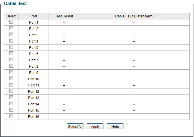
Follow these steps to diagnose the cable:
1) Select your desired ports for test. Click Apply to test cables connected to the selected ports.
2) Check the test results in the table.
|
Port |
Displays the port number. |
|---|---|
|
Test Result |
Displays the connection status of cables. Test results include Normal, Close (or Short), Open and Crosstalk. Normal : The cable is connected normally. Close (or Short): A short circuit is being caused by abnormal contact of wires in the cable. Open: No device is connected to the other end or the connection is broken. Crosstalk: Impedance mismatch due to the poor quality of the cable. |
|
Cable Fault Distance (m) |
If the connection status is Normal, here displays the length of the cable. If the connection status is Close (or Short), Open, or Crosstalk, here displays the length from the port to the trouble spot. |
4.5 Configuring Loop Prevention
Choose the menu Monitoring > Loop Prevention to load the following page.
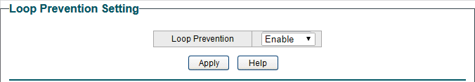
 Follow these steps to configure loop prevention:
1) Enable or disable loop prevention.
|
Loop Prevention |
Enable or disable the loop prevention feature globally. |
|---|
2) Click Apply.
4.6 Appendix: Default Parameters
Default settings of Port Mirror are listed in the following table.
|
Parameter |
Default Setting |
|
Port Mirror |
Disable |
Default settings of Loop Prevention are listed in the following table.
|
Parameter |
Default Setting |
|
Loop Prevention |
Enable |
Chapter 5 Configuring VLAN
5.1 Overview
VLAN (Virtual Local Area Network) is a network technique that solves broadcasting issues in local area networks. It is usually applied in the following occasions:
■ To restrict broadcast domain: VLAN technique divides a big local area network into several VLANs, and all VLAN traffic remains within its VLAN. It reduces the influence of broadcast traffic in Layer 2 network to the whole network.
■ To enhance network security: Devices from different VLANs cannot achieve Layer 2 communication, and thus users can group and isolate devices to enhance network security.
■ For easier management: VLANs group devices logically instead of physically, so devices in the same VLAN need not be located in the same place. It eases the management of devices in the same work group but located in different places.
There are 3 types of VLAN modes supported on the switch:
■ MTU VLAN
MTU VLAN (Multi-Tenant Unit VLAN) defines an uplink port which will build up several VLANs with each of the other ports. Each VLAN contains two ports, the uplink port and one of the other ports in the switch, so the device connected to the uplink port can communicate with the device connected to any other port, but devices connected to other ports cannot communicate with each other.
■ Port Based VLAN
VLANs are divided based on ports. In port based VLAN mode, each port can only be added to one VLAN.
■ 802.1Q VLAN
The IEEE 802.1Q protocol defines a new format of VLAN data frame (Tagged Frame). As the following figure shows, compared to the traditional Ethernet data frame (Untagged Frame), the VLAN data frame (Tagged Frame) adds a VLAN tag.
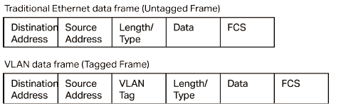
On receiving a tagged frame, the switch checks the VID (VLAN ID) contained in the VLAN tag to determine which VLAN the frame belongs to. On receiving an untagged frame, the switch will first insert a VLAN tag to the frame, using the PVID (Port VLAN ID) of the port as its VID, and then forward it as a tagged frame.
Note:
● The switch works in one and only one VLAN mode at any time. When a specific VLAN mode is enabled, the other two VLAN modes will be disabled automatically and the corresponding VLAN configuration will be lost.
● The switch supports up to 32 VLANs simultaneously.
5.2 Configuring MTU VLAN
Choose the menu VLAN > MTU VLAN to load the following page.
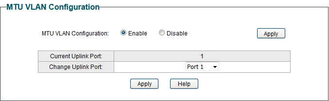

Follow these steps to configure MTU VLAN:
1) Select MTU VLAN configuration as Enable. Click Apply.
|
MTU VLAN Configuration |
Enable or disable the MTU VLAN mode. |
|---|
2) In the table below, change the uplink port from the drop-down list according to your needs. Click Apply.
|
Change Uplink Port |
Select the desired uplink port from the drop-down list. The uplink port will build up several VLANs with each of the other ports. |
|---|
5.3 Configuring Port Based VLAN
Choose the menu VLAN > Port Based VLAN to load the following page.
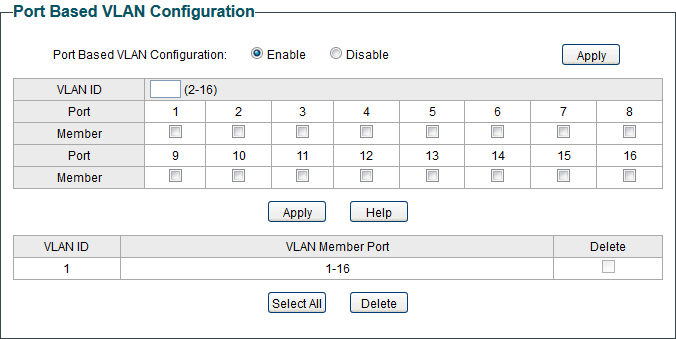

Follow these step to configure port based VLAN:
1) Select the port based VLAN configuration as Enable. Click Apply.
|
Port Based VLAN Configuration |
Enable or disable the port based VLAN mode. |
|---|
2) Select the ID for the VLAN and ports to add to the VLAN. Click Apply.
|
VLAN ID |
Select the ID for the VLAN which you want to add ports to. |
|---|---|
|
Member |
Select the ports to add to the VLAN. |
3) In the table below, you can verify the configuration result of port based VLAN. You can delete a VLAN as you wish by selecting the VLAN and clicking Delete.
Note:
● By default, all the ports are added to VLAN 1.
● Once a port is added to another VLAN, it is deleted from the original VLAN automatically.
● Once a port is removed from all the other VLANs, it is added to VLAN 1 automatically.
● VLAN 1 includes at least one port and cannot be deleted.
5.4 Configuring 802.1Q VLAN
To complete the 802.1Q configuration, follow these steps:
1) Configure the VLAN, including creating a VLAN and adding the ports to the VLAN.
2) Configure the PVID.
5.4.1 Configuring the VLAN
Choose the menu VLAN > 802.1Q VLAN to load the following page.
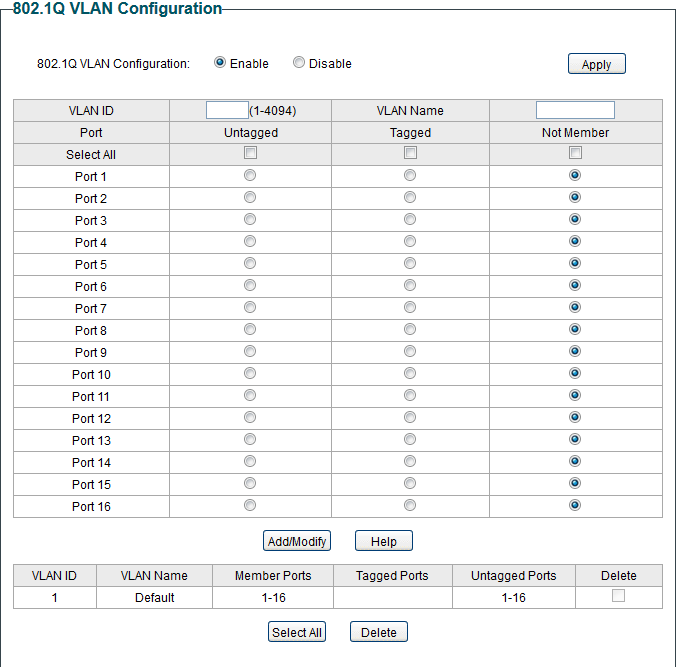
Follow these steps to configure the VLAN:
1) Select the 802.1Q VLAN Configuration as Enable. Click Apply.
|
802.1Q VLAN Configuration |
Enable or disable the 802.1Q VLAN mode. |
|---|
2) Enter a VLAN ID and a VLAN name for identification. Select the untagged port(s) and the tagged port(s) respectively to add to the created VLAN based on the network topology. Click Add/Modify.
|
VLAN ID |
Enter a VLAN ID, which rages from 1 to 4094. |
|---|---|
|
VLAN Name |
Enter a VLAN name for identification. The VLAN name should not be more than 10 characters using digits, letters, hyphens and underlines only. |
|
Untagged / Tagged / Not Member |
Set the port as an untagged port, as a tagged port or not as a member port in the VLAN. Untagged: Select the egress rule of the port as Untagged. An untagged port will forward frames after removing the VLAN tags. Tagged: Select the egress rule of the port as Tagged. A tagged port will forward frames with the current VLAN tags remained. Not Member: The port that is not selected as a member will not forward frames in the target VLAN. |
3) In the table below, you can verify the configuration result of 802.1Q VLAN. You can delete a VLAN as you wish by selecting the VLAN and clicking Delete.
Note:
● By default, all the ports are added to VLAN 1.
● The port can be removed from VLAN 1 only when the port is also a member of the other VLANs.
● Once a port is removed from all the current VLANs, it is added to VLAN 1 automatically.
● VLAN 1 cannot be deleted.
5.4.2 Configuring the PVID
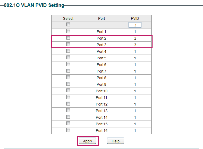
Choose the menu VLAN > 802.1Q PVID Setting to load the following page.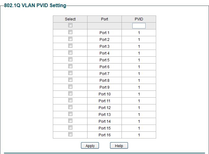
Follow these steps to configure the PVID:
1) Select the ports and set the PVID for the ports.
|
PVID |
Set the PVID for the ports. The PVID ranges from 1 to 4094. |
|---|
2) Click Apply.
Note:
● The PVID configuration will take effect only when 802.1Q VLAN mode is enabled.
● You can specify a PVID only when the corresponding VLAN exists.
5.5 Configuration Example for 802.1Q VLAN
5.5.1 Network Requirements
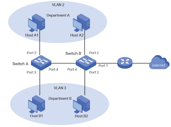
As the following figure shows, a company has two departments. Hosts of the same department are located in different places and connected to different switches respectively.
It’s required that:
■ Hosts of both departments can access the internet.
■ Hosts of the same department can communicate with each other, but hosts of different departments cannot.
5.5.2 Configuration Scheme
To implement the above requirements, configure 802.1Q VLAN on both switches.
■ Create VLAN 2. On Switch A, add port 2 and port 4 to VLAN 2, while on Switch B, add port 1, port 2 and port 4 to VLAN 2.
■ Create VLAN 3. On Switch A, add port 3 and port 4 of Switch A to VLAN 3, while on Switch B, add port 1, port 3 and port 4 to VLAN 3.
■ Configure the default VLAN 1 to make sure the router can communicate with all ports of the two switches.
Tables below show configurations of VLANs on each switch.
|
Switch |
Ports in VLAN 1 |
Ports in VLAN 2 |
Ports in VLAN 3 |
|
Switch A |
2, 3, 4 |
2, 4 |
3, 4 |
|
Switch B |
1, 2, 3, 4 |
1, 2 ,4 |
1, 3, 4 |
|
Switch |
Port |
Egress Rule |
PVID |
|
Switch A |
2 |
Untagged |
2 |
|
3 |
Untagged |
3 |
|
|
4 |
Tagged |
1 |
|
|
Switch B |
1 |
Untagged |
1 |
|
2 |
Untagged |
2 |
|
|
3 |
Untagged |
3 |
|
|
4 |
Tagged |
1 |
Note:
If a port is connected to terminal devices like computers, add the port to the corresponding VLANs as an untagged port, because terminal devices typically do not support VLAN tags.
5.5.3 Configuration Steps
Demonstrated with TL-SG1016PE, the following section provides configuration steps. The configuration steps on both switches are similar. Here we take Switch A for example.
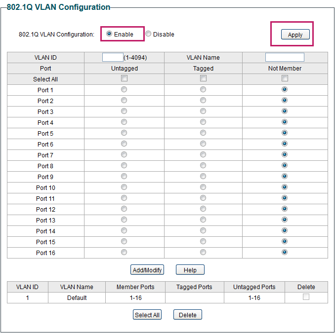
1) Choose the menu VLAN > 802.1Q VLAN to load the following page. Select 802.1Q VLAN configuration as Enable. Click Apply.
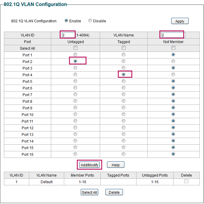
 2) Choose the menu VLAN > 802.1Q VLAN to load the following page and create VLAN 2. Specify VLAN ID as 2, add port 2 to the VLAN as an untagged port, and add port 4 to the VLAN as a tagged port. Click Add/Modify.

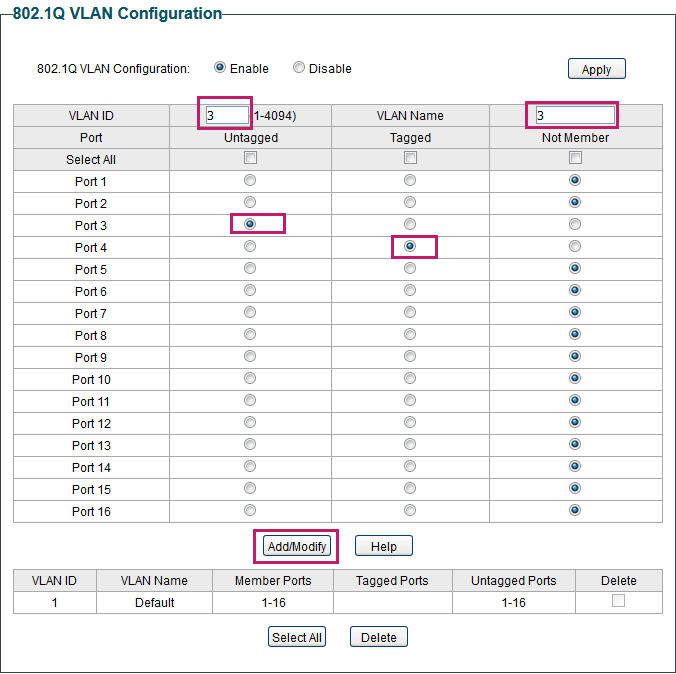
3) Choose the menu VLAN > 802.1Q VLAN to load the following page and create VLAN 3. Specify VLAN ID as 3, add port 3 to the VLAN as an untagged port, and add port 4 to the VLAN as a tagged port. Click Add/Modify.
 4) Choose the menu VLAN > 802.1Q VLAN PVID Setting to load the following page. Specify the PVID of port 2 as 2 and click Apply. Specify the PVID of port 3 as 3 and click Apply.

5.6 Appendix: Default Parameters
Default settings of VLAN are listed in the following tables.
Default Settings of MTU VLAN Configuration
|
Parameter |
Default Setting |
|
MTU VLAN Configuration |
Disable |
Default Settings of Port Based VLAN Configuration
|
Parameter |
Default Setting |
|
Port Based VLAN Configuration |
Enable |
|
VLAN ID |
1 |
|
VLAN Member Port |
1-5 |
Default Settings of 802.1Q VLAN Configuration
|
Parameter |
Default Setting |
|
802.1Q VLAN Configuration |
Disable |
Default Settings of 802.1Q VLAN PVID Configuration
|
Parameter |
Default Setting |
|
PVID |
1 |
Chapter 6 Configuring QoS
6.1 QoS
6.1.1 Overview
With network scale expanding and applications developing, internet traffic is dramatically increased, thus resulting in network congestion, packet drops and long transmission delay. Typically, networks treat all traffic equally on FIFO (First In First Out) delivery basis, but nowadays many special applications like VoD, video conferences, VoIP, etc. require more bandwidth or shorter transmission delay to guarantee the performance.
With QoS (Quality of Service) technology, you can classify and prioritize network traffic to provide differentiated services for certain types of traffic.
6.1.2 Supported Features
With the QoS feature, You can configure QoS Basic, Bandwidth Control and Storm Control on the switch to maximize the network performance and bandwidth utilization.
QoS Basic
The switch classifies the ingress packets, maps the packets to different priority queues and then forwards the packets to implement QoS function.
Bandwidth Control
Bandwidth Control functions to control the ingress traffic rate and egress traffic rate on each port via configuring the available bandwidth of each port. In this way, the network bandwidth can be reasonably distributed and utilized.
Storm Control
Storm Control function allows the switch to monitor broadcast packets, multicast packets and UL-frames (Unknown unicast frames) in the network. If the transmission rate of the packets exceeds the limit, the packets will be automatically discarded to avoid network broadcast storm.
6.2 Configuring Basic QoS
Configuration Guidelines
Select the QoS mode according to your network requirements. Three QoS modes are supported on the switch: Port Based, 802.1P Based and DSCP Based.
■ Port Based
The port based QoS mode supports four priority queues, which are labeled as 1 (Lowest), 2 (Normal), 3 (Medium) and 4 (Highest).
In this mode, the switch prioritizes packets according to their ingress ports, regardless of the packet field or type.
■ 802.1P Based
802.1P defines the first three bits in 802.1Q Tag as PRI field. The PRI values are from 0 to 7. The tagged packets are mapped to 4 priority levels based on the PRI value (Lowest=0, 1; Normal=2, 3; Medium=4, 5; Highest=6, 7).
In this mode, the switch only prioritizes packets with VLAN tag, regardless of the IP header of the packets.
■ DSCP/802.1P Based
DSCP priority determines the priority of packets based on the ToS (Type of Service) field in their IP header. RFC2474 re-defines the ToS field in the IP packet header as DS field. The first six bits of the DS field is used to represent DSCP priority. The DSCP values are from 0 to 63. The IP packets are mapped to 4 priority levels based on the DSCP value (Lowest=0-15; Normal=16-31; Medium=32-47; Highest=48-63).
In this mode, the switch prioritizes packets with IP header based on DSCP priority first. Then, the switch prioritizes packets with VLAN tag but without IP header base on the PRI field. Finally, the switch prioritizes packets without VLAN tag or IP header based on port priority.
6.2.1 Configuring QoS in Port Based Mode
Choose the menu QoS > QoS Basic to load the following page.
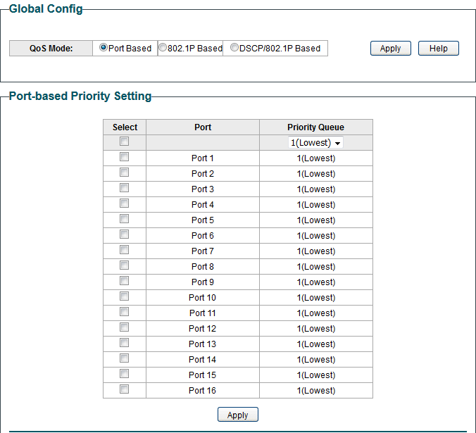
Follow these steps to configure QoS in port based mode:
1) In the Global Config section, select QoS mode as Port Based. Click Apply.
|
QoS Mode |
Select the QoS mode. Port Based: In port based mode, the switch prioritizes packets according to their ingress ports, regardless of the packet field or type. |
|---|
2) In the Port-based Priority Setting section, select the desired ports and specify the priority queue for the ports. Click Apply.
|
Priority Queue |
Specify the priority queue that the packets from the port are mapped to. The priorities are labeled as 1, 2, 3 and 4. Among them, the bigger value means the higher priority. |
|---|
6.2.2 Configuring QoS in 802.1P Based Mode
Choose the menu QoS > QoS Basic to load the following page.
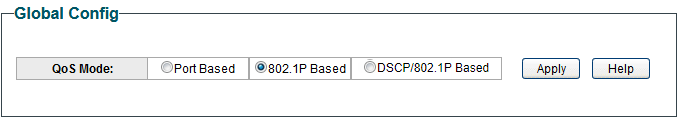
Follow these steps to configure QoS in 802.1P based mode:
1) Select QoS mode as 802.1P Based.
|
QoS Mode |
Select the QoS mode. 802.1P Based: In 802.1P based mode, the tagged packets are mapped to 4 priority levels based on the Pri value in 802.1Q tag (Lowest = 0, 1; Normal = 2, 3; Medium= 4, 5; Highest = 6, 7). The switch only prioritizes packets with VLAN tag, regardless of the IP header of the packets. |
|---|
2) Click Apply.
6.2.3 Configuring QoS in DSCP/802.1P Based Mode
Choose the menu QoS > QoS Basic to load the following page.
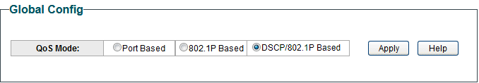 Follow these steps to configure QoS in DSCP/802.1P based mode:
1) Select QoS mode as DSCP/802.1P Based.
|
QoS Mode |
Select the QoS mode from the drop-down list. DSCP/802.1P Based: In DSCP/802.1P based mode, the IP packets are mapped to 4 priority levels based on the DSCP value (Lowest= 0-15; Normal = 16-31; Medium = 32-47; Highest = 48-63). The switch prioritizes packets with IP header based on DSCP priority first. Then, the switch prioritizes packets with VLAN tag but without IP header base on the PRI field. Finally, the switch prioritizes packets without VLAN tag or IP header based on port priority. |
|---|
2) Click Apply.
6.3 Configuring Bandwidth Control
Choose the menu QoS > Bandwidth Control to load the following page.
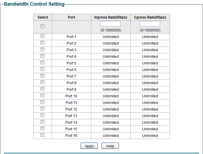
 Follow these steps to configure bandwidth control:
1) Select the desired ports and configure the ingress rate and egress rate for the ports.
|
Ingress Rate (Kbps) |
Configure the bandwidth for receiving packets on the port. If the rate for receiving packets on the port exceeds the ingress rate, the packets will be discarded. |
|---|---|
|
Egress Rate (Kbps) |
Configure the bandwidth for sending packets on the port. If the rate for sending packets on the port exceeds the egress rate, the packets will be discarded. |
2) Click Apply.
Note:
● For a port, the ingress rate control feature and the storm control feature cannot be enabled at the same time. If you enable ingress rate control for a port, storm control will be disabled for that port automatically.
● When egress rate is set for one or more ports, it is recommended to disable the flow control on each port to ensure the switch works normally.
● For ports in the same LAG, bandwidth control should be configured the same to ensure a successful port aggregation.
6.4 Configuring Storm Control
Choose the menu QoS > Storm Control to load the following page.

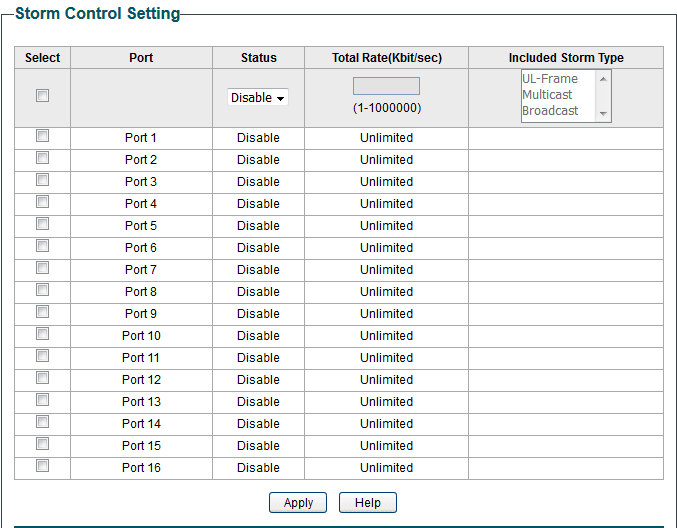
Follow these steps to configure storm control:
1) Select the desired ports and configure the upper rate limit for forwarding broadcast packets, multicast packets and UL-frames (Unknown unicast frames).
|
Status |
Enable or disable the storm control feature for the port. |
|---|---|
|
Total Rate (Kbit/sec) |
Specify the upper rate limit for receiving the packets on the port. If the rate for receiving the packets on the port exceeds the total rate, the packets will be discarded. |
|
Included Storm Type |
Select to filter broadcast/multicast/UL frame in the network. If the transmission rate of the chosen packets exceeds the total rate, the packets will be automatically discarded to avoid network broadcast storm. It is multi-optional. UL-Frame: If UL-Frame packets traffic exceeds the rate on the port, they will be discarded. Multicast: If multicast packets traffic exceeds the rate on the port, they will be discarded. Broadcast: If broadcast packets traffic exceeds the rate on the port, they will be discarded. |
2) Click Apply.
Note:
● For a port, the storm control feature and the ingress rate control feature cannot be enabled at the same time. If you enable storm control for a port, ingress rate control will be disabled for that port automatically.
● For ports in the same LAG, storm control should be configured the same to ensure a successful port aggregation.
6.5 Configuration Example for Basic QoS
6.5.1 Network Requirements
As shown below, both RD department and Marketing department can access the internet. When congestion occurs, the traffic from two departments can both be forwarded and the traffic from the Marketing department should take precedence.
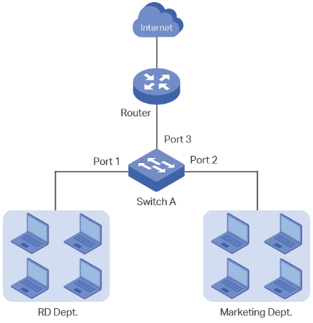
6.5.2 Configuration Scheme
To implement this requirement, you can configure QoS in port based mode to put the packets from the Marketing department into the queue with the higher priority than the packets from the RD department. Follow these procedures to configure QoS in port based mode.
1) Enable port based mode.
2) Map port 1 and port 2 to different priorities queues.
Demonstrated with TL-SG1016PE, the following section provides configuration steps.
6.5.3 Configuration Steps
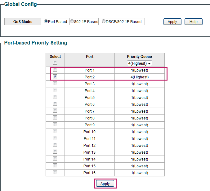
1)Choose the menu QoS > QoS Basic to load the following page. In the Global Config section, select QoS mode as Port Based. Click Apply.
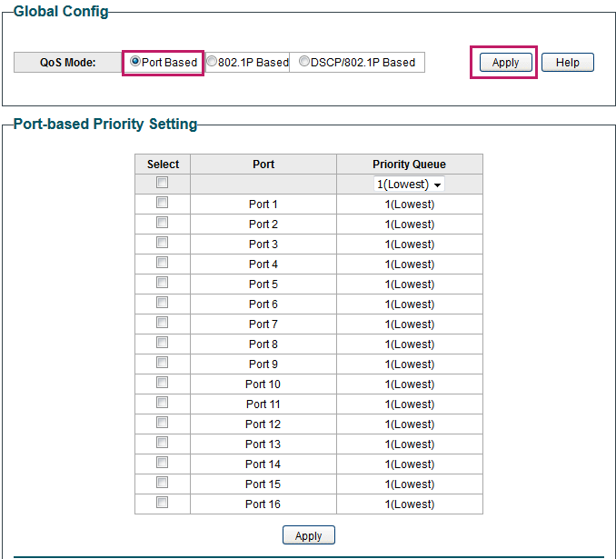
2) In the Port Based Priority Setting section, specify the priority queue for port 1 as 1 (Lowest) and click Apply. Specify the priority queue for port 2 as 4 (Highest) and click Apply.

6.6 Appendix: Default Parameters
Default settings of QoS basic configuration are listed in the following table.
Default Settings of QoS Basic Configuration
|
Parameter |
Default Setting |
|
QoS Mode |
DSCP/802.1P Based |
|
Priority Queue |
1 (Lowest) |
Default settings of Bandwidth Control configuration are listed in the following table.
Default Settings of Bandwidth Control Configuration
|
Parameter |
Default Setting |
|
Ingress Rate (Kbps) |
Unlimited |
|
Egress Rate (Kbps) |
Unlimited |
Default settings of Storm Control configuration are listed in the following table.
Default Settings of Storm Control Configuration
|
Parameter |
Default Setting |
|
Status |
Disable |
|
Total Rate (Kbit/sec) |
Unlimited |
Chapter 7 Configuring PoE (Only for Certain Devices)
7.1 Overview
Note:
● The PoE Config is only available on TL-SG1016PE, TL-SG1218MPE and TL-SG1428PE. For TL-SG108PE, TL-SG105PE and TL-SG1210MPE, this feature is not supported.
PoE (Power over Ethernet) is a remote power supply function. With this function, the switch can supply power to the connected devices over twisted-pair cables.
Some devices such as IP phones, access points (APs) and cameras may be located far away from the AC power source in actual use. PoE can provide power for these devices without requiring to deploy power cables. This allows a single cable to provide both data connection and electric power for the device.
■ PSE
Power sourcing equipment (PSE) is a device that provides power for PDs on the Ethernet, for example, the PoE switch. PSE can detect the PDs and determine the device power requirements.
■ PD
Powered device (PD) is a device receiving power from the PSE, for example, IP phones and access points. According to whether PDs comply with IEEE standard, they can be classified into standard PDs and non-standard PDs. Only standard PDs can be powered via TP-Link PoE switches.
7.2 Configuring PoE
Choose the menu PoE > PoE config to load the following page.

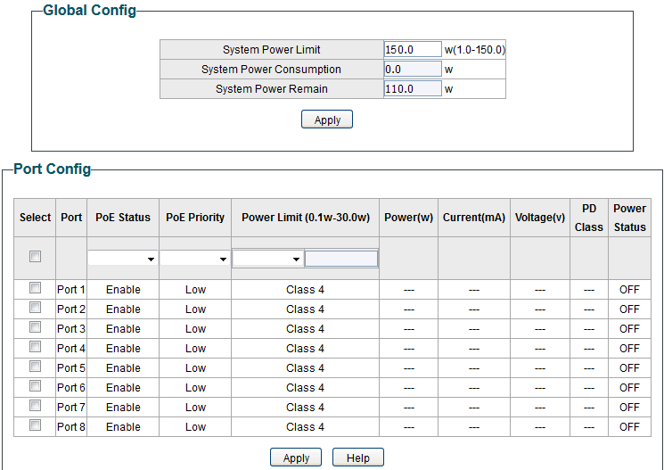
Follow these steps to configure PoE:
1) In the Global Config section, you can view the current PoE parameters. You can configure the System Power Limit. Click Apply.
|
System Power Limit |
Configure the maximum power the PoE switch can supply. |
|---|---|
|
System Power Consumption |
Displays the real-time system power consumption of the PoE switch. |
|
System Power Remain |
Displays the real-time system remaining power of the PoE switch. |
2) In the Port Config section, select the ports you want to configure and specify the parameters. Click Apply.
|
PoE Status |
Enable or disable the PoE function on corresponding ports. A port can supply power to the PD when its status is enable. |
|---|---|
|
PoE Priority |
Select the priority level for the corresponding port. When the supply power exceeds the system power limit, the switch will power off PDs on low-priority ports to ensure stable running of other PDs. |
|
Power Limit (0.1 w-30 w) |
Specify the maximum power the corresponding port can supply. The following options are provided: Class 1: The maximum power that the port can supply is 4 W. Class 2: The maximum power that the port can supply is 7 W. Class 3: The maximum power that the port can supply is 15.4 W. Class 4: The maximum power that the port can supply is 30 W. Manual: You can enter a value manually. |
|
Power (w) |
Displays the real-time power supply of the port. |
|
Current (mA) |
Displays the real-time current of the port. |
|
Voltage (v) |
Displays the real-time voltage of the port. |
|
PD Class |
Displays the class which the linked PD belongs to. |
|
Power Status |
Displays real-time power status of the port. |
7.3 Configuring PoE Auto Recovery
With PoE Auto Recovery enabled, the switch detects the link status between the ports and connected PDs. The switch pings the IP addresses of PDs constantly. If a PD loses connection, the switch will reboot it automatically.
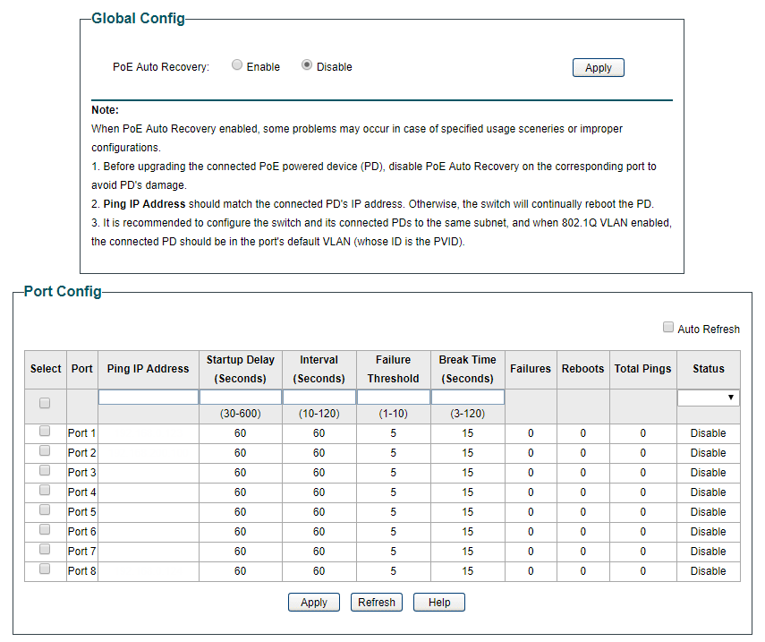
Choose the menu PoE > PoE Auto Recovery to load the following page.

 Follow these steps to enable PoE Auto Recovery and configure the parameters:
1) In the Global Config section, enable or disable PoE Auto Recovery. Click Apply.
|
PoE Auto Recovery |
Enable or disable PoE Auto Recovery globally. |
|---|
Note:
● Before upgrading the connected PoE powered device (PD), disable PoE Auto Recovery on the corresponding port to avoid PD’s damage.
● It is recommended to configure the switch and its connected PDs to the same subnet, and when 802.1Q VLAN enabled, the connected PD should be in the port’s default VLAN (whose ID is the PVID). For detailed configurations, refer to Configuring 802.1Q VLAN.
2) In the Port Config section, select the desired ports and specify the parameters. Click Apply.
|
Ping IP Address |
Enter the IP address of the PD connected to the port. Ping IP Address should be the same as the connected PD’s IP address. Otherwise, the switch will continually reboot the PD. |
|---|---|
|
Startup Delay |
Specify how long the switch waits for the connected PD’s rebooting before the switch starts to ping the PD’s IP address. |
|
Interval |
Specify the interval between two consecutive ping packets. |
|
Failure Threshold |
Specify the threshold for ping failures. If the switch fails to get the ping response from the PD on the port, the switch will retry until the number of ping failures reaches the threshold, then the switch reboots the PD. |
|
Break Time |
Specify how soon the switch reboots the PD after the number of ping failures reaches the threshold. |
|
Failures |
Display the number of ping failures since the latest reboot of the PD. It will be reset when the PD responds to the ping packet or is rebooted. |
|
Reboots |
Display the number of PD’s reboots. It will be reset after reaching 9,999 or when the switch is rebooted. |
|
Total Pings |
Display the total number of ping packets that the switch sends to the connected PD. It will be reset after reaching 9,999 or when the switch is rebooted. |
|
Status |
Enable or disable PoE Auto Recovery on the desired ports. To make it enabled, enable PoE Auto Recovery both globally and on the port. |
7.4 Appendix: Default Parameters
Default settings of PoE Config are listed in the following table.
Default Settings of PoE Config
|
Parameter |
Default Setting |
|
Global Config |
|
|
System Power Limit |
150.0 W |
|
Port Config |
|
|
PoE Status |
Enabled |
|
Startup Delay |
Low |
|
Interval |
Class 4 |
Default settings of PoE Auto Recovery are listed in the following table.
Default Settings of PoE Auto Recovery
|
Parameter |
Default Setting |
|
Global Config |
|
|
PoE Auto Recovery |
Disabled |
|
Port Config |
|
|
Ping IP Address |
None |
|
Startup Delay |
60 seconds |
|
Interval |
60 seconds |
|
Failure Threshold |
5 |
|
Break Time |
15 seconds |
|
Status |
Disabled |