Table of Contents
DS-ETPA-1U Installation and User Guide
About This Guide
This User Guide provides information for managing TP-Link DeltaStream Chassis Embedded Telecom Power products via the web UI. Please read this guide carefully before operation.
Intended Readers
This User Guide is intended for network managers familiar with IT concepts and network terminologies.
Conventions
When using this guide, notice that:
-
Features available for Embedded Telecom Power products may vary due to your region, hardware version, and device model. All images, steps, and descriptions in this guide are only examples and may not reflect your actual experience.
-
The information in this document is subject to change without notice. Every effort has been made in the preparation of this document to ensure accuracy of the contents, but all statements, information, and recommendations in this document do not constitute the warranty of any kind, express or implied. Users must take full responsibility for their application of any products.
-
This guide uses the specific formats to highlight special messages. The following table lists the notice icons that are used throughout this guide.
Bold font indicates a button, toolbar icon, menu or menu item.
| Note | Remind to take notice. The note contains the helpful information for a better use of the product. |
|---|---|
| Configuration Guidelines | Provide tips for you to learn about the feature and its configurations. |
More Information
-
For technical support, the latest version of the User Guide and other information, please visit https://www.tp-link.com/support.
-
To ask questions, find answers, and communicate with TP-Link users or engineers, please visit https://community.tp-link.com to join TP-Link Community.
Introduction
Overview
TP-Link DeltaStream Chassis Embedded Telecom Power is designed to provide flexible and stable power supply. It is an AC input and DC-output telecom power system. The power supports the following features:
-
Supports up to 3 pluggable modules, with an input range of 100-240V~ 50/60Hz
-
All power supply modules support current sharing or redundancy.
-
Two independently controlled DC outputs, with an output voltage of 53.5V. Single DC output max power is 1550W; total for two DCs is 2400W.
-
Supports functions of input and output overcurrent protection, overvoltage protection, undervoltage protection, overpower protection, overtemperature protection, etc.
-
Supports remote monitoring for output's port voltage and current power, and port power allocation control.
-
Suitable for DS-P8000-X7 and other rack-mount DC power input devices
Appearance
Front Panel
The front panel of DS-ETPA-1U is shown as the following figure. The figure is for demonstration purposes only. Your device may differ in appearance from the depicted.
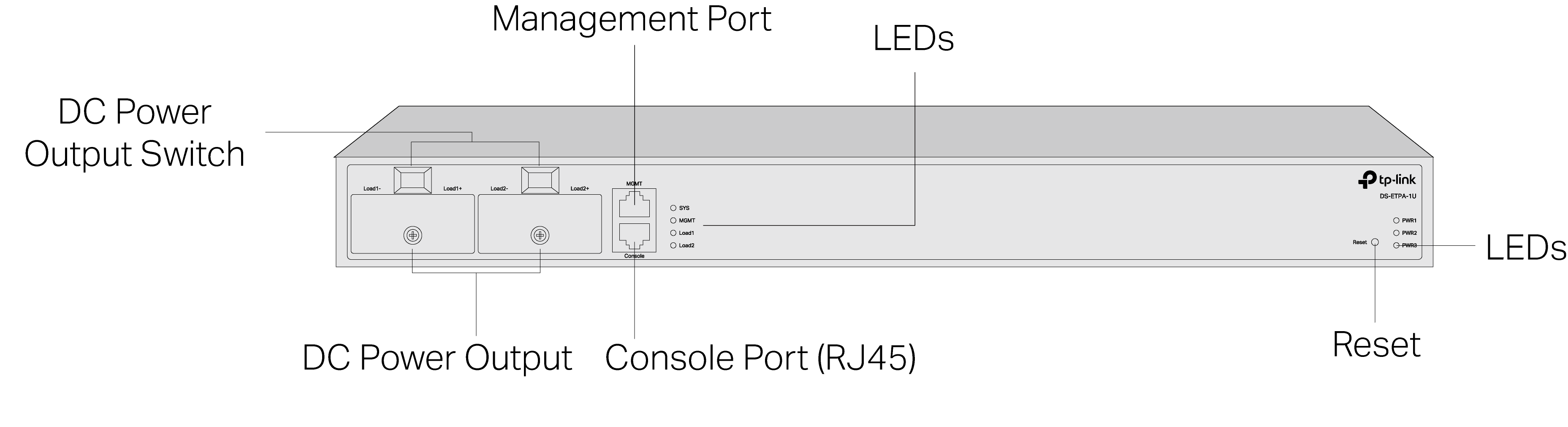
DC Power Output
It is recommended to use at least an 8 AWG power cord or a thicker one to connect the power supply equipment and the DC power input of the device, and make sure that the connection is reliable.
When connecting, make sure that the positive and negative poles of the power supply equipment correspond to the positive and negative poles of the device, and that the power supply meets the requirement of the input. An all-pole mains switch in accordance with IEC/EN/UL 62368-1 Annex L shall be incorporated in the electrical installation of the building. And the disconnect device shall have a contact separation at least 2.0mm.
Power Switch
After connecting the power cord, press the rocker switch to turn on or off the corresponding DC Power Output.
Management Port
Connects to a management terminal like a PC via an Ethernet cable, and then the network manager can configure and monitor the device via CLI.
Console Port
Connects with a computer for monitoring and configuring the power system.
Reset
If you want to reset the device, press and hold the reset button for more than 5 seconds.
| LED | Indication |
|---|---|
| SYS | Green Flashing: The power system works properly. Green Flashing Quickly: The power system is upgrading or being reset to the default settings. Yellow Flashing: The power system works properly but there is an alarm. Yellow On: The power system works improperly. Off: The power system is powered off or power supply is abnormal. |
| MGMT | Green On: A device is linked to the port. Green Flashing: Transmitting or receiving data. Off: No device is linked to the port. |
| Load 1 Load 2 |
Green On: The corresponding DC power output works properly. Yellow Falshing: The corresponding DC power output works properly but there is an alarm. Yellow On: The corresponding DC power output works improperly. Undervoltage protection/overvoltage protection/overcurrent protection/overpower protection/overtemperature protection. Off: The corresponding DC power output is powered off. |
| PWR1 PWR2 PWR3 |
Green On: The power supply works properly. Green Flashing: The power supply module is not plugged in properly or not compatible with the power system. Yellow On: The power supply works properly but the power system is powered by the other power supply. Yellow Flashing: The power supply module is plugged in properly but there's is no AC power input; abnormal power supply. Off: No power supply module is inserted. |
Rear Panel
The rear panel of DS-ETPA-1U is shown as the following figure. The figure is for demonstration purposes only. Your device may differ in appearance from the depicted.

Caution:
-
It is not permissible to leave the power slots empty during operation. A power module (which can remain inactive) or a baffle must be inserted to prevent disruption of the overall heat dissipation airflow and compromise of the cooling function.
-
It is strictly forbidden to plug or unplug the power module with power on, as this may cause personal injury.
Grounding Terminal
The device already comes with lightning protection mechanism. You can also ground the device through the PE (Protecting Earth) cable of AC cord or with Ground Cable. For detailed lightning protection measures, refer to the Lightning Protection Guide.
AC Power Socket
Plug the negative connector of the power cord directly into the AC power socket and plug the positive connector into an AC power outlet. Make sure that the voltage of the power supply meets the requirement of the input (100‑240V~ 50/60Hz).
AC Power Input
Connects to the power cord for power supply modules. It is recommended to use an 12 AWG power cord to connect the power supply equipment and the DC power input of the device, and make sure that the connection is reliable. When connecting, make sure that the positive and negative poles of the power supply equipment correspond to the positive and negative poles of the device, and that the power supply meets the requirement of the input. An allpole mains switch in accordance with EN 62368-1 2014 Annex L shall be incorporated in the electrical installation of the building. And the disconnect device shall have a contact separation at least 1.5mm.
Power Supply Module
The pluggable power supply module PSM900-AC is an AC-input power supply module. It can convert the input voltage to 53.5V with the maximum output power of 900 W.
Note: The PWR1 is the main power supply module, and the priority among the main power supply module and the backup ones can be configured according to actual needs.
Installation
Package Contents
Make sure that the package contains the following items. Please contact your distributor, if any of the listed items is damaged or missing. The figures are for demonstration only. The actual items may differ in appearance and quantity from the depicted.
| One Embedded Telecom Power | 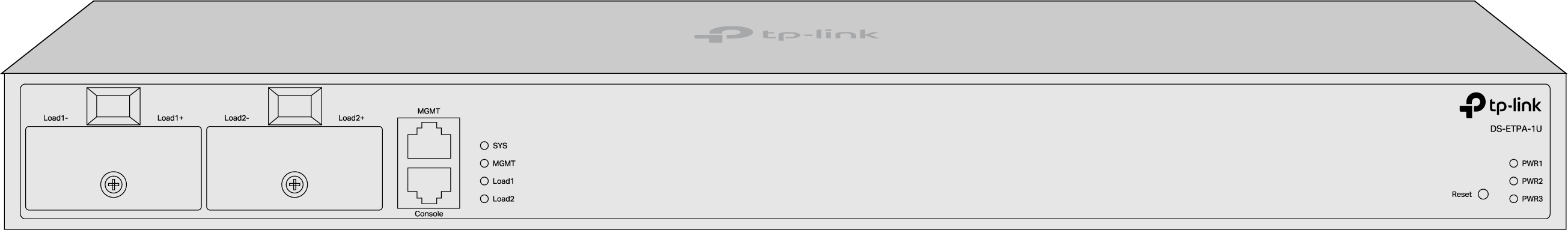 |
|---|---|
| Installation Guide |  |
| Power Cord and Console Cable | 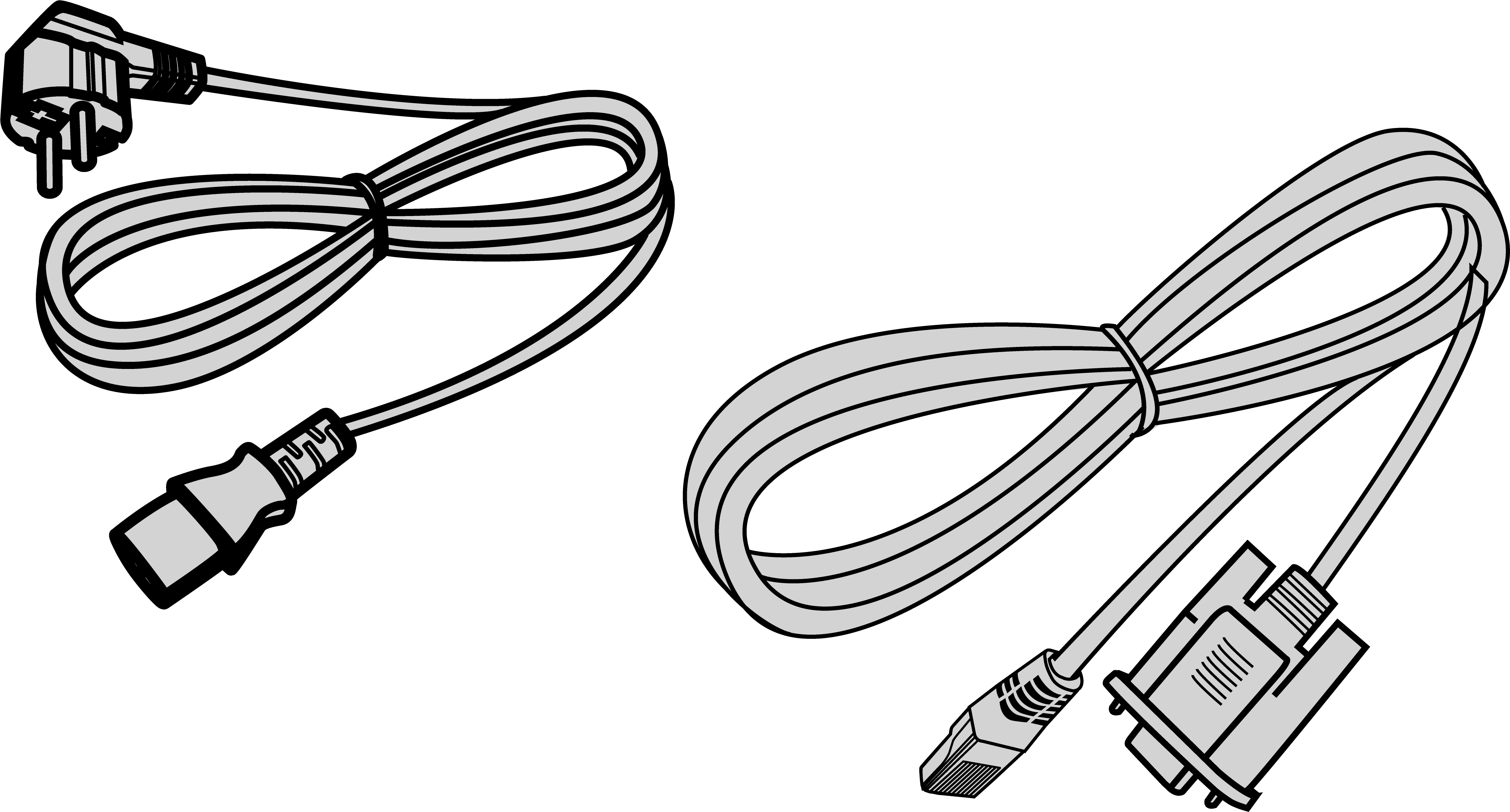 |
| Ring Terminal Power Cable |  |
| Mounting Screws and Nuts | 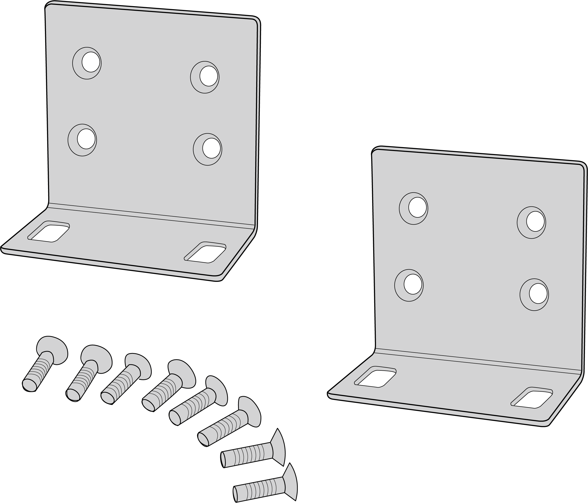 |
Safety Precautions
To avoid any device damage and bodily injury caused by improper use, you should observe the following rules.
Safety Precautions
-
Keep the power off during the installation.
-
Wear an ESD-preventive wrist strap, and make sure that the wrist strap has a good skin contact and is well grounded.
-
Use only the power cord provided with the device.
-
Make sure that the supply voltage matches the specifications indicated on the rear panel of the device.
-
Ensure that the device is installed in a well-ventilated environment and its ventilation hole is not blocked.
-
Do not open or remove the cover of the device.
-
Before cleaning the device, cut off the power supply. Do not clean it by the waterish cloth, and never use any other liquid cleaning method.
-
Place the device with its bottom surface downward.
-
The rating of the external overcurrent protective device shall not exceed 50 A.
-
Plug the product into the wall outlets with earthing connection through the power supply cord.
-
The socket-outlet shall be installed near the equipment and shall be easily accessible.
Site Requirements
- Temperature/Humidity
Keep the equipment room at an appropriate level of temperature and humidity. Too much or too little humidity may lead to bad insulation, leakage of electricity, mechanical property changes, and corrosion. High temperatures may accelerate aging of the insulation materials, significantly shortening the service life of the device. To find out the best temperature and humidity conditions for the device, check the Appendix B Specifications.
- Clearness
The dust accumulated on the device can be absorbed by static electricity and result in poor contact of metal contact points. Some measures have been taken for the device to prevent static electricity, but too strong static electricity can cause deadly damage to the electronic elements on the internal circuit board. To avoid the effect of static electricity on the operation of the device, attach much importance to the following items:
• Dust the device regularly, and keep the indoor air clean.
• Keep the device well grounded and ensure that the static electricity has been transferred.
- Electromagnetic Interference
Electronic elements including capacitance and inductance on the device can be affected by external interferences, such as conducted emission by capacitance coupling, inductance coupling, and impedance coupling. To decrease the interferences, make sure to take the following measures:
• Use the power supply that can effectively filter interference from the power grid.
• Keep the device far from high-frequency and strong-current devices such as radio transmitting station.
• Use electromagnetic shielding when necessary.
- Lightning Protection
Extremely high voltage currents can be produced instantly when lightning occurs and the air in the electric discharge path can be instantly heated up to 20,000 °C. As this instant current is strong enough to damage electronic devices, more effective lightning protection measures should be taken.
• Ensure that the rack and the device are well earthed.
• Make sure the power socket has a good contact with the ground.
• Keep a reasonable cabling system and avoid induced lightning.
• Use the signal SPD (Surge Protective Device) when wiring outdoor.
Note: For detailed lightning protection measures, refer to the Lightning Protection Guide.
Installation Site
When installing the device on a rack or a flat workbench, attach much importance to the following items:
-
Install the device with its bottom surface facing down only.
-
This equipment is not suitable for use in locations where children are likely to be present.
-
The rack or workbench is flat, stable, and sturdy enough to support the weight of 9.5 kg at least.
-
The rack or workbench has a good ventilation system. The equipment room is well ventilated.
-
The rack is well grounded. Keep the device less than 1.5 meters away from the power socket.
Installation Tools
-
Phillips screwdriver
-
ESD-preventive wrist wrap
-
Cables
Note: The Phillips screwdriver and cables are not included with our product. If needed, you can purchase them separately.
Product Installation
Rack Installation
To install the device in an EIA standard-sized, 19-inch rack, follow the instructions described below:
1. Check the efficiency of the grounding system and the stability of the rack.
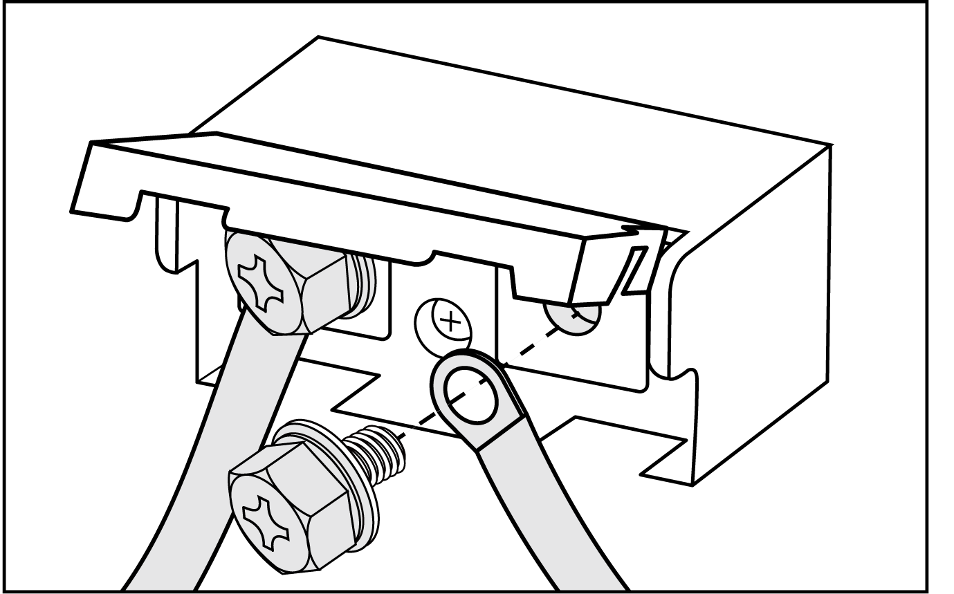
2. Secure the supplied rack-mounting brackets to each side of the device with supplied screws, as illustrated in the following figure.
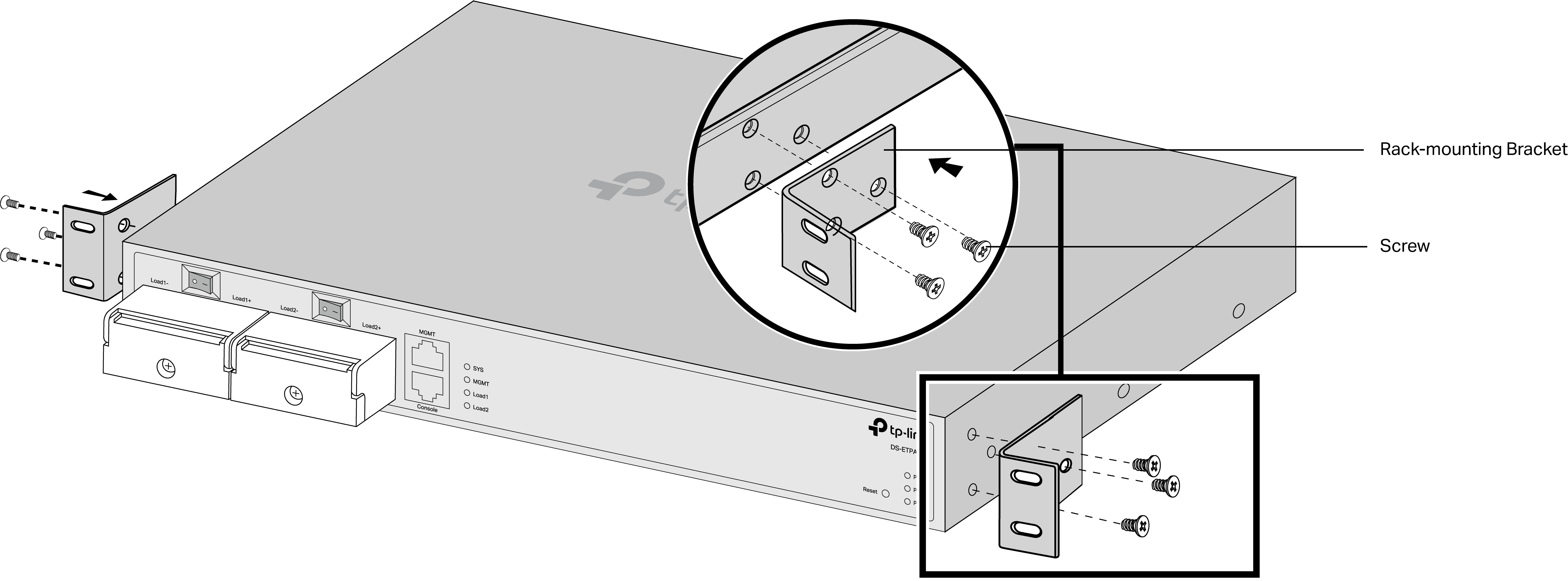
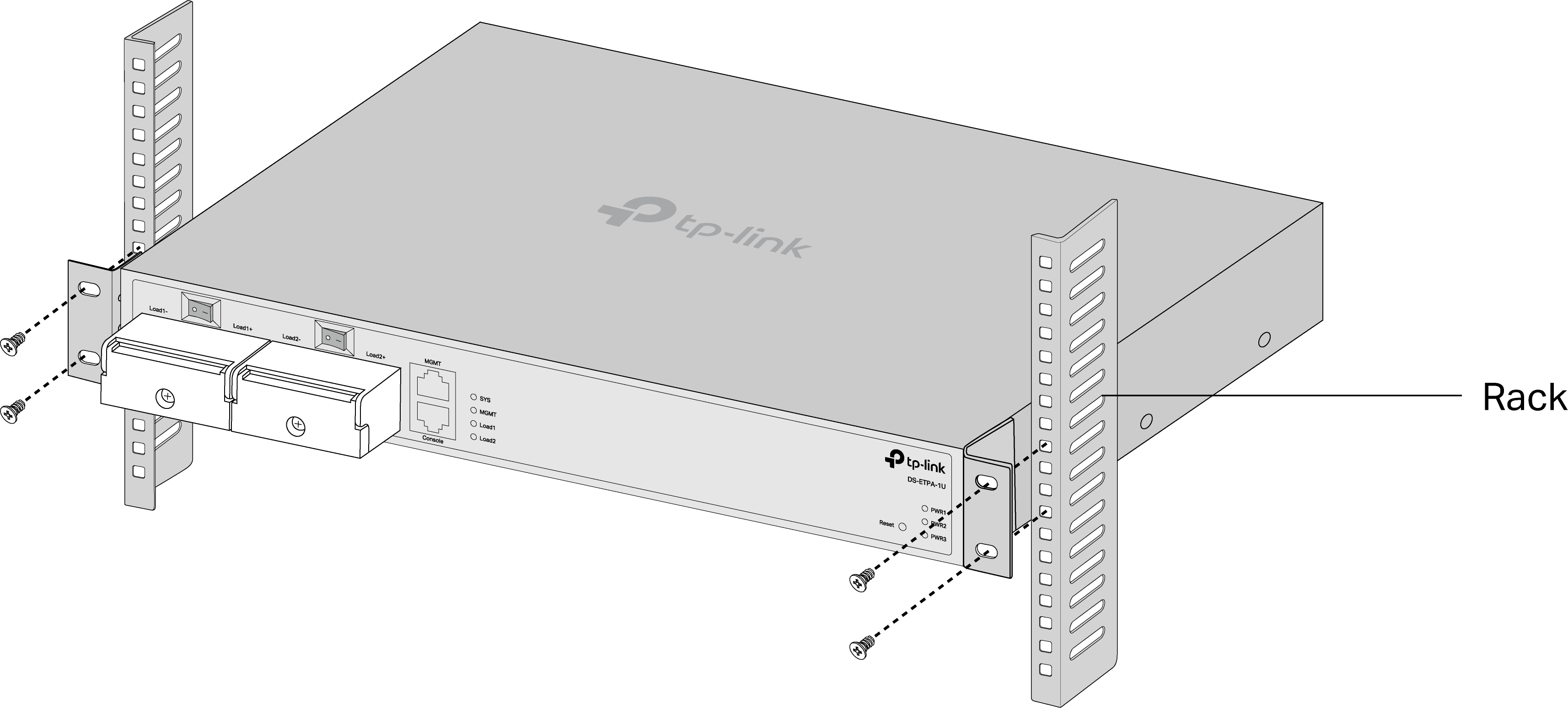
3. Since the product is heavy, it is necessary to install joists on the rack first, so that the brackets and product can be secured later. After the brackets are attached to the device, use suitable screws (not provided) to secure the brackets to the rack, as illustrated in the following figure.
Caution:
-
Leave 5 to 10 cm gaps around the devices for air circulation.
-
Avoid placing heavy things on the device.
-
Place the device with its bottom facing downwards.
-
Mount devices in sequence from the bottom to top of the rack and ensure a certain clearance between devices for the purpose of heat dissipation.
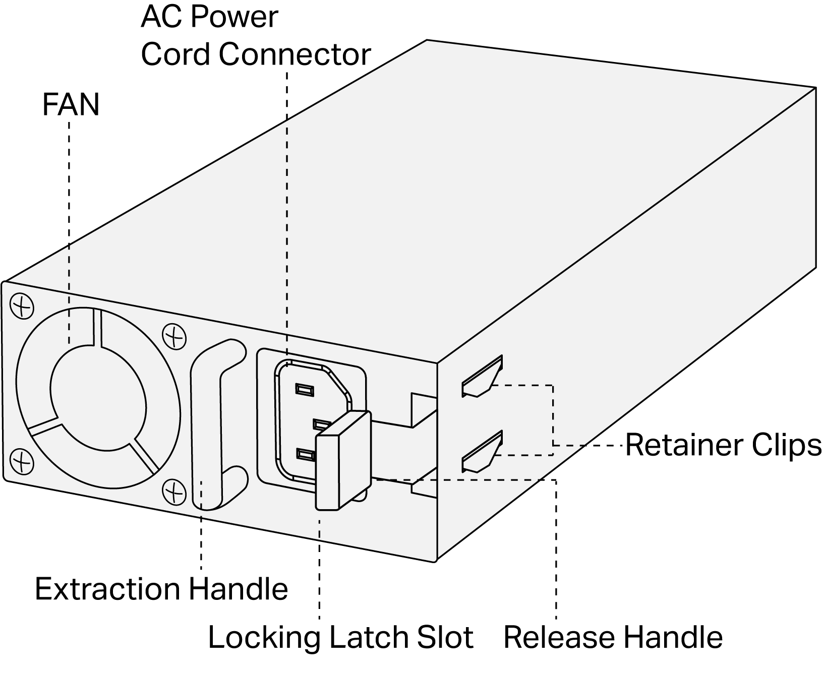
Power Supply Module Installation
The power sytem shipped with three PSM900-AC power supply modules installed. They look like below, and the images may differ from your actual product.
If you need to replace the power supply module, please follow the steps:
1. Wear an ESD-preventive wrist strap, and make sure that it has good skin contact and is well grounded.
2. Press the extraction handle of the module with one hand, and press the power system using your other hand. Gently pull out the provided module in along the slot guide rail.
3. Press the extraction handle of the module with one hand, and hold the bottom of the module using your other hand. Gently push the new module in along the slot guide rail.
4. Release the extraction handle to fix the power supply module in place.
Caution:
-
Do not plug the power cord until the power supply module installation is completed.
-
When installing a power supply module, make sure it is set correctly in the operation of installation.
-
Do not use too much force in the installation. If resistance is encountered or positions of the power supply module appear larger during installation, you must first remove the module and then reinstall the module.
-
If the Retainer Clips cannot spring up naturally and the power module is blocked, it may be due to the power supply module is not installed properly. Please check carefully.
Connection
Port Connection
CLI (Command Line Interface) enables you to manage the device, thus you can load the CLI after connecting the PCs or Terminals to the console port on the device via the provided RJ45 console cable.
Connect the RJ45 console port of the device with your computer by the console cable as the following figure shows.
Verify Installation
After completing the installation, verify the following items:
-
There should be 5 to 10 cm of clearance around the device for ventilation and make sure the air flow is adequate.
-
The voltage of the power supply meets the requirement of the input voltage of the device.
-
The power socket, device and rack are well grounded.
-
The device is correctly connected to other network devices.
-
A dummy panel must be installed in the empty slot. After the dummy panel is pulled out, if the board is not inserted in the corresponding slot, it should be inserted back in time.
Power On
Plug the female connector of the provided power cord into the power socket of the device and plug the positive connector into a power outlet as the following figure shows. Make sure that the voltage of the power supply meets the requirement of the input voltage (100‑240 V~ 50/60 Hz).
Caution:
1. The figure is to illustrate the application and principle. The provided plug, socket and/or module in your region may differ from the figures above.
2. Generally PWR1 takes priority over PWR2 and PWR3.
Login and Management
Login via Management Port
1. Connect the MGMT port of the device to the management PC using an Ethernet cable.
2. Set the IP address of the PC as 192.168.0.x/24 (x is a number between 2 and 254).
3. You can access the device using the CLI:
Use a telent to access 192.168.0.1 to open the CLI of the device. Log in to the CLI. Create an account and password for your first login. Noting that the password should contain letters, numbers, and special symbols, and must be no less than 10 characters.
Note: For more detailed CLI instructions, please refer to DS-ETPA-1U_CLI Guide.
Login via Console Port
1. Connect the Console port of the device to the management PC using an RJ45 console cable.
2. Start the terminal emulation program (such as the Hyper Terminal) on the PC and configure the terminal emulation program as follows:
| Baud Rate | Data Bits | Parity | Stop Bits | Flow Control |
|---|---|---|---|---|
| 115200 bps | 8 | None | 1 | None |
Troubleshooting
Q1. What could I do if I forgot the username and password of the device?
You can reset the device by holding the reset button for more than 5 seconds. Note that all the configurations will be lost after resetting the device.
Q2. Why does the PWR LED work abnormally?
The PWR LED should be lit up when the power system works normally. If the PWR LED worked abnormally, take the following steps:
Make sure that the power cable is connected properly, and the power contact is normal.
Make sure the voltage of the power supply meets the requirement of the input voltage of the switch.