Catalogue
Lightning Protection Guide
COPYRIGHT & TRADEMARKS
Specifications are subject to change without notice. 
 is a registered trademark of TP-Link Systems Inc. Other brands and product names are trademarks or registered trademarks of their respective holders.
No part of the specifications may be reproduced in any form or by any means or used to make any derivative such as translation, transformation, or adaptation without permission from TP-Link Systems Inc. Copyright © 2025 TP-Link Systems Inc. All rights reserved. http://www.tp-link.com
Intended Readers
This guide is intended for network engineers and network administrators.
Conventions
When using this guide, please note that the figures are used for demonstration only.
The information in this document is subject to change without notice. Every effort has been made in the preparation of this document to ensure the accuracy of the contents, but all statements, information, and recommendations in this document do not constitute a warranty of any kind, expressed or implied. Users must take full responsibility for their application of any products
1. Introduction
Lightning is a violent discharge phenomenon that occurs in the Earth's atmosphere and can cause severe natural disasters. With the advancement of science and technology, a larger communication network has been built by computers, various networks, and communication devices. As the network scale expands, the threat of lightning to network equipment becomes increasingly prominent. It not only causes direct damage to devices but can also lead to the interruption of the entire network system, resulting in incalculable economic losses. Therefore, it is necessary to understand lightning and correctly install and use network equipment.
This manual will introduce the basic knowledge of lightning protection for rack-mounting installation of TP-Link network products, including the overall principles, methods, and precautions of lightning protection, and provide detailed explanations on lightning protection measures such as proper cabling, correct grounding, equipotential bonding, and the use of lightning arresters.
1.1 Scope of Application
This manual applies to the following products: TP-Link rack-mount devices.
This manual is for technicians who install, use, and maintain the above products.
1.2 Conventions
This manual uses the following formats to highlight special messages:
|
Warning: This is to remind you to be careful; otherwise, the device may not be in a protected state, resulting in device damage or malfunction. |
|---|
|
Note: This is to provide supplementary information. |
1.3 Overview
Chapter 1: Introduction to the manual.
Chapter 2: Overview of lightning protection. This chapter will briefly describe the hazards of lightning and the basic principles of lightning protection.
Chapter 3: Proper cabling. This chapter will help you properly cable your devices for lightning protection.
Chapter 4: Grounding requirements. This chapter will briefly describe the grounding requirements and provide on-site grounding solutions.
Chapter 5: Equipotential bonding.
Chapter 6: Using lightning arresters.
1.4 Related Standards
This manual has referenced the following standards:
· IEC61643-21:2000 Surge protective devices connected to telecommunications and signalling networks – Performance requirements and testing methods
· ITU-T K.27 Bonding configurations and earthing inside a telecommunication building
· ITU-T K.35 Bonding configurations and earthing at remote electronic sites
· ITU-T K.46 Protection of telecommunication lines using metallic symmetric conductors against lightning-induced surges
· ITU-T K.66 Protection of customer premises from overvoltages
· IEC62305-1 Protection against lightning –Part 1: General principles
· IEC62305-2 Protection against lightning –Part 2: Risk management
· IEC62305-3 Protection against lightning –Part 3: Physical damage to structures and life hazard
· IEC62305-4 Protection against lightning – Part 4: Electrical and electronic systems within structures
· IEC 60364-5-54 Electrical installations of buildings – Part 5-54 Selection and erection of electrical equipment – Earthing arrangement, protective conductors and protective bonding conductors
2. Overview of Lightning Protection
This chapter will introduce the characteristics of lightning, explain the hazards of lightning strikes to network equipment, and propose the main principles of lightning protection.
2.1 Lightning Characteristics
Lightning carries immense power. The following facts offer a clear, intuitive understanding:
· Strong current and voltage: The current of ordinary lightning can reach tens of thousands or even hundreds of thousands of amperes, and the voltage can reach millions of volts. Such extreme current and voltage can instantly ionize the air, creating a conductive path for discharge;
· Huge energy release: It is estimated that the energy released by a lightning strike is about 500 million joules, equivalent to 14,000 kilowatt-hours of electricity, which can keep a 100-watt light bulb lit for about 160 years;
· Extremely high temperature: When lightning strikes, the temperature inside its channel can instantly rise to 30,000 degrees Celsius, which is more than five times the temperature of the sun's surface;
· Huge destructive power: Lightning can damage tall structures and generate powerful electrical noise, leading to equipment failure and widespread power outages.
Lightning has such tremendous power, while the operating voltage of electronic communication equipment is constantly decreasing with the number of devices is increasing, leading the equipment prone to damage from lightning strikes.
2.2 Types of Lightning Strikes
Lightning strikes have two types: direct lightning strikes and induced lightning.
2.2.1 Direct Lightning Strikes
Direct lightning strikes refer to the phenomenon where discharge occurs directly between clouds and protruding objects on the ground such as buildings or trees. As the immense current of lightning can directly enter the ground through these objects, lightning often causes severe damage to objects along the discharge path and even leads to personal injury or death.
If lightning directly strikes power lines or communication lines entering a building from outside, it will cause overvoltage and overcurrent at the equipment power supply or network interfaces, thereby damaging the equipment.
Ground potential rises may also result in equipment damage. A ground potential rise occurs when a direct lightning strike hits the building's lightning arrester (lightning rod or lightning protection net). This will cause a massive current to flow through the grounding system, generating a voltage difference across the grounding resistor. This voltage difference will be introduced into the equipment through the ground wire, causing damage.
2.2.2 Induced Lightning
Induced lightning refers to the phenomenon where discharges occur between clouds or between clouds and the nearby ground, causing overvoltage and overcurrent in conductors like power lines, communication lines, and metal pipes. Compared to direct lightning strikes, induced lightning has a higher probability of occurrence and is more widespread.
During a lightning discharge, the rapidly changing current induces a strong electromagnetic field in the surrounding space, causing induced overvoltage and overcurrent in power lines and communication lines, thereby damaging equipment.
2.3 How Lightning Damages Equipment
Lightning can damage equipment in the following ways:
· When a lightning arrester or its surrounding objects are struck by direct lightning through an air-termination system, the ground potential will increase, causing damage to the equipment.
· When the lightning current is led into the ground through the lightning down conductor, the rapid current changes generate strong electromagnetic fields. These electromagnetic pulses can couple into equipment wiring, potentially causing damage to the equipment.
· Direct or induced lightning strikes the far end of the power line and communication lines connected to the equipment, causing overvoltage and overcurrent to flow along the lines, damaging the equipment.
2.4 Equipment Lightning Protection Principles
There are two basic principles for equipment lightning protection. First, equipment lightning protection should be systematic, which means the equipment and its operating environment should be considered as a whole for lightning protection. Second, all lightning protection measures are "probabilistic"; that is, taking lightning protection measures cannot guarantee that the equipment is 100% safe, but it can reduce the risk of equipment failure or damage.
Therefore, both external and internal lightning protection measures are needed to fully safeguard the building's electronic information system, as shown in the following:
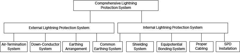
2.4.1 External Lightning Protection
External lightning protection measures, composed of air-termination system, down conductors system, and earthing arrangement, are mainly used to protect against direct lightning strikes.
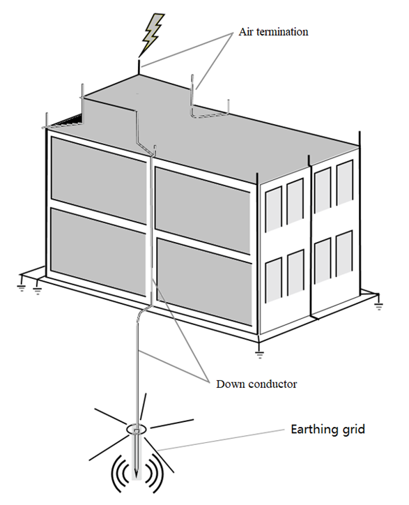
Air-termination system are usually located on top of buildings. Their principle is to use their protruding position above the protected objects to guide lightning to themselves and receive direct lightning discharges. Lightning currents enter the ground through the down conductors and earthing arrangement.
For TP-Link product users, if conditions permit, it is advised to install the equipment in a building with the above-mentioned external lightning protection measures, and have professional technicians regularly check the reliability of the building's lightning protection facilities. The lightning protection design of the building should comply with relevant national standards.
2.4.2 Internal Lightning Protection
Internal lightning protection measures, composed of common earthing system, shielding system, equipotential bonding system, proper cabling and SPD(lightning arrester) installation, are mainly used to reduce and prevent the electromagnetic effects of lightning currents to reduce device damage brought by lightning strikes.
When installing and cabling devices, users should pay special attention to the requirements of the above measures. The subsequent chapters of this manual will introduce the above measures in detail.
3. Proper Cabling
3.1 General Requirements for Cabling
Proper cabling of communication cables and power supply lines can effectively reduce the damage caused by induced lightning strikes. In an actual network environment, cabling may need to be done indoors or outdoors depending on the location of the network equipment. The requirements in these two cases have large differences.
|
Warning: · Communication cables should be routed indoors, avoiding overhead routing or over-the-eaves routing to effectively reduce the damage of induced lightning strikes on equipment. · If the device is installed indoors, the AC power line should not be directly introduced from outdoors to avoid damage caused by lightning strikes. · Ethernet cables and power lines should not be routed close to each other or parallel to each other over long distances. |
|---|
3.1.1 Outdoor Cabling Requirements
Under normal circumstances, avoid running cables outdoors. If it cannot be avoided, use optical-fiber cables as the communication cables. Since optical fibers usually do not have conductors (if there are metal reinforcement cores or other conductors in the optical cables, the conductors should be directly grounded at the entrance), they will not be struck by lightning and there is no need to install lightning arresters. Thus, the optical fibers can be used for overhead routing.
If cables have to be run outdoors, strictly comply with the following requirements:
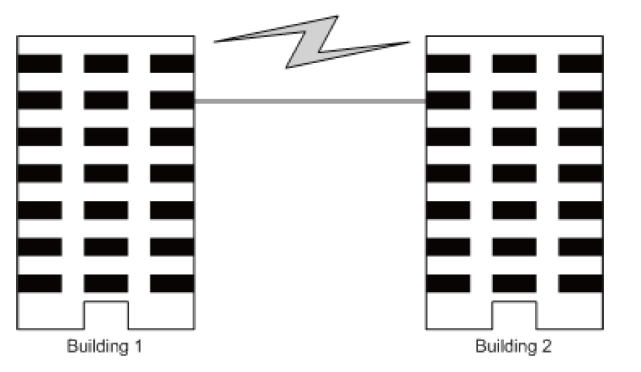
· It is prohibited to run overhead cables between buildings without taking any protective measures, as shown in the figure below:
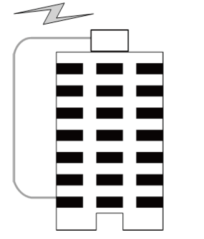
· It is prohibited to connect devices on different floors by wiring along the outer wall of the building, as shown in the following figure:
· If cables have to be run outdoors, it is advised to bury them all underground and bring them indoors from underground. It is recommended to bury a steel wire along the outside of a pipeline, with one end of the steel wire connected to the lightning protection ground of the building to provide shielding. Before connecting to devices, install a signal lightning arrester at the corresponding end.
· If cables have to be run overhead outdoors, it is advised that the cables pass through a metal pipe at least 15 meters long before entering the room, and both ends of the metal pipe should be grounded. Before connecting to devices, install a signal lightning arrester on the corresponding port.
· If fully shielded network cables are used, they do not need to be laid in the pipe. However, be sure to ground the shielding layer of the network cables reliably to ensure shielding. Before connecting to devices, install a signal lightning arrester on the corresponding port.
· When connecting outdoor wires without any protective measures to devices, be sure to install a power lightning arrester or a signal lightning arrester on the corresponding interface.
|
Note: Lightning arrester is not provided with the product. Users need to prepare by themselves. For the installation guide of lightning arresters, refer to Chapter 6 of this manual. |
|---|
3.1.2 Indoor Cabling Requirements
When cabling indoors, keep communication cables away from down conductors, power lines, transformers, motors, and other sources of high-frequency interference. Avoid bundling different cable types together.
· Trunk cables should be laid in metal raceways located in the electrical shaft of buildings. When laying cables, pay attention to reducing the loop area formed by the cables themselves.
· The distance between the Ethernet cables and other pipelines should meet the following requirements:
| Other Pipelines | Ethernet Cable | |
|---|---|---|
| Min. Parallel Net Length L (mm) | Min. Parallel-overlapping Net Height H (mm) | |
| Down-conductor | 1000 | 300 |
| PE | 50 | 20 |
| Service pipe | 150 | 20 |
| Compressed air pipe | 150 | 20 |
| Thermal pipe (not wrapped) | 500 | 500 |
| Thermal pipe (wrapped) | 300 | 300 |
| Gas pipe | 300 | 20 |
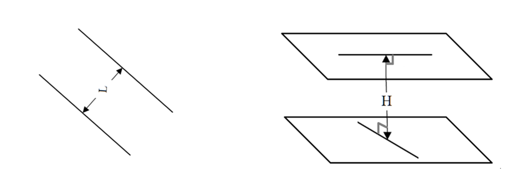
The min. parallel net length (L) is the shortest distance between two or more cables laid in the same direction along parallel planes and the min. parallel-overlapping net height (H) is the shortest clearance between cables when cables from different directions intersect on the same plane, as shown in the following.
|
Warning: The above requirements are specific to the cables without metal raceways. If any requirements cannot be met, consider using steel pipes or metal raceways for shielding. |
|---|
· The distance between communication cables and power lines of high-power electrical devices should meet the following requirements:
| Cable | Pave Way | Min. Parallel Length (mm) |
|---|---|---|
| >5kVA powerline | Parallel cabling | 130 |
| One is in the grounded metal raceway or metal pipe | 70 | |
| Both are in the grounded metal raceway or metal pipe | 10 | |
| 2 to 5kVA powerline | Parallel cabling | 300 |
| One is in the grounded metal raceway or metal pipe | 150 | |
| Both are in the grounded metal raceway or metal pipe | 80 | |
| >5kVA powerline | Parallel cabling | 600 |
| One is in the grounded metal raceway or metal pipe | 300 | |
| Both are in the grounded metal raceway or metal pipe | 150 |
· The distance between communication cables and high-power electrical devices should meet the following requirements:
| Device | Min. Distance (m) |
|---|---|
| Switch case | 1.00 |
| Transformer room | 2.00 |
| Elevator tower | 2.00 |
| Air-conditioner room | 2.00 |
3.2 Cable Installation
Before connecting cables, estimate the cable length to ensure a reasonable length for connection.
After installing all the cables, block the empty space in the cable holes in a timely manner to prevent rodent infestations.
· Installing power lines
Connect one end of the power line to the device and the other to the power strip. Fold the excess part into an S shape and fix it inside the rack. Keep it separate from other cables at a distance of more than 5 cm.
· Installing communication cables
Indoor and outdoor communication cables should be installed and bundled separately and should be led out from different rack outlet holes to user terminals or cascade devices.
· Installing optical-fiber cables
The optical-fiber cables should be directly connected to the photoelectric converter from the optical ports and hung inside the rack in coils. The optical-fiber cables cascaded with other devices should be wrapped in PVC pipes to avoid being pulled and stretched.
|
Warning: Optical fiber itself is not a conductor and will not sense or transmit overvoltage. However, the metal reinforcement cores and metal sheaths of the optical-fiber cables (armored components to protect the optical fiber) are very susceptible to sensing and transmitting lightning overvoltage and must be properly handled. The metal reinforcement cores and metal sheaths of the optical cables entering and leaving the station should be grounded on an ODF rack or fiber splice box after entering the equipment room. |
|---|
· Installing ground wires
One end of the ground wire should be connected to the ground terminal of the equipment and the other connected to the ground bar. The distance between the ground wire and the communication cable should be no less than 5 cm.
4. Grounding Requirements
Grounding quickly discharges overvoltage and overcurrent from lightning strikes and is essential for personal safety. Proper and reliable grounding at the installation site must be ensured.
4.1 General Requirements for Grounding
All metal parts of the equipment that are not normally energized should be grounded, including the grounding terminal on the equipment casing, the metal sheath or shielding layer of the equipment's outdoor cable, the lightning arrester installed on the equipment cable, the PE line of the AC power supply, the positive pole of the -48V DC power supply, etc. To ensure reliable grounding of equipment, pay attention to the following requirements:
· In any case, short and thick copper core wires should be used for grounding to ensure safety. The cross-sectional area of the copper core should meet the following requirements:
| Circuit Rated Current (A) | Min. Conductor Size | |
|---|---|---|
| Cross-Sectional Area (mm²) | AWG (Cross-Sectional Area mm²) | |
| ≤16 | Not specified | Not specified |
| >16 ~ ≤25 | 1.5 | 14 (2) |
| >25~≤32 | 2.5 | 12 (3) |
| >32~≤40 | 4.0 | 10 (5) |
| >40~≤63 | 6.0 | 8 (8) |
| >63~≤80 | 10 | 6 (13) |
| >80~≤100 | 16 | 4 (21) |
To ensure the lightning protection grounding effect, it is recommended that the cross-sectional area of the grounding cable that connects the rack grounding bar and the building grounding is greater than or equal to 6 mm2 and the length of the grounding cable does not exceed 30 m.
|
Note: Not all products are delivered with ground wires. If necessary, prepare the ground wires by yourself according to the above requirements. |
|---|
· It is strictly prohibited to connect two ground wires together, or add any switches or fuses.
· Reasonably estimate the length of the ground wire before wiring. While meeting the distance requirements, use the shortest possible ground wire.
· Ensure good electrical contact for the grounding points at both ends of the ground wire. Carry out corrosion resistance treatment (electroplating or coating) if necessary.
· The ground wire should not run parallel to or twist around the signal cable.
4.2 On-Site Grounding Solution
Grounding methods should be selected based on the device’s environment. Using a TP-Link campus access switch as an example, three grounding methods are shown below. Among them, grounding via a grounding bar offers better lightning protection. Choose the most suitable method based on the specific environmental conditions.
· If a grounding bar is available in the device installation environment, it is recommended to connect the device to the grounding bar after ensuring its reliability, as shown in the following figure:
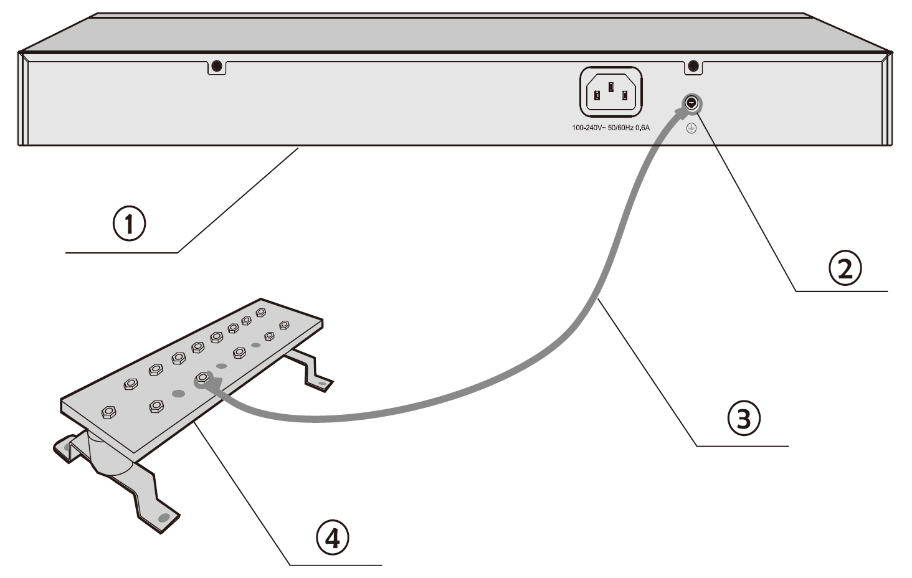
① Device (Rear Panel) ② Grounding Terminal ③ Ground Cable ④ Grounding Bar
· If a grounding bar is unavailable but nearby soil allows for burying a grounding electrode, it is recommended to drive an angle steel or steel pipe at least 2.5 m into the ground. The angle steel should be no smaller than 50 mm × 50 mm × 5 mm, and the steel pipe should have a wall thickness of at least 3.5 mm. The upper end of the grounding electrode should be at least 0.7 m from the ground. The device ground wire should be connected to the angle steel through electric welding. Welded joints and rust-prone areas should be treated with anti-corrosion measures.
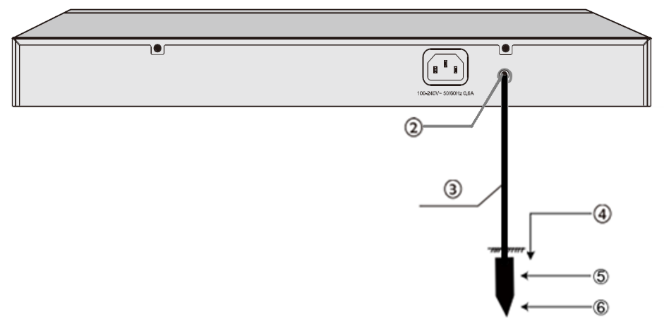
① Device (Rear Panel) ② Grounding Terminal ③ Ground Cable ④ Ground ⑤ Welding Point ⑥ Grounding Electrode
· If a grounding bar and buried grounding electrode are unavailable, it is recommended to use the PE (protective earth) wire of the AC power supply for grounding through the power cord provided with the device.
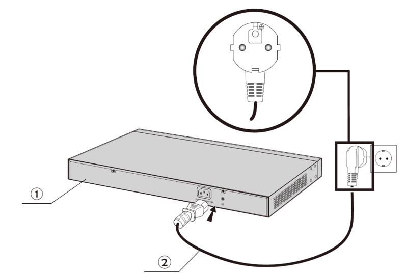
① Device (Rear Panel) ② AC Power Cord (with PE cable)
|
Warning: When grounding via the AC power supply's PE wire, first ensure the socket’s PE wire is reliably grounded. If not, it must be securely grounded before use. |
|---|
5. Equipotential Bonding
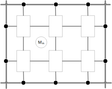
Equipotential bonding connects all grounding systems in a building into a unified network, either through a shared grounding system or via conductive links above or below ground. During a lightning strike, the resulting high voltage appears simultaneously across all ground wires, minimizing potential differences and greatly reducing the risk of breakdown between systems (because the potential of each system is the same, there is no current between two points, and the potential difference is zero).
5.1 General Requirements for Equipotential Bonding
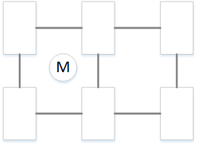
Multiple devices in the same network need to be bonded equipotentially, including metal casings, cabinets, racks, metal pipes, troughs, metal outer layers of shielded cables, protective grounding bars, power supply PE lines, interconnected devices, lightning arresters, etc. They should all be connected to the grounding reference point of the S-shape structure (star structure) or to the grid of the M-shape structure (mesh structure) at the shortest distance. The equipotential bonding network should be connected to the common grounding system. The schematic diagram is demonstrated as follows:
|
Star Structure (S) |
Mesh Structure (M) |
|
|---|---|---|
| Basic Equipotential Bonding Diagram | 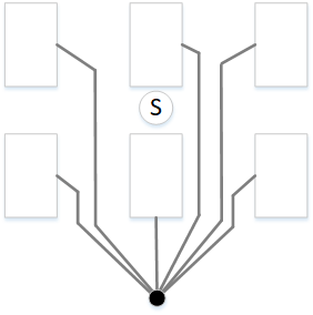 |
 |
| Equipotential Bonding to Common Grounding System | 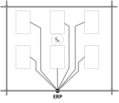 |
 |
|
Warning: · The equipotential bonding conductor must be a copper core grounding wire with a cross-sectional area of at least 6 mm2. · The equipotential bonding conductor should be as short as possible. · Use a grounding bar (ring) as an equipotential bonding point. |
|---|
5.2 Equipotential Bonding Solution
· For equipotential bonding of multiple devices in a large network, refer to the topology in 5.1 General Requirements for Equipotential Bonding.
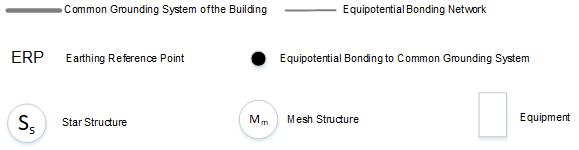
· For devices close to each other, refer to the following topology. After the connection, use a multimeter to measure each equipotential grounding point to ensure good contact and low impedance.
① Grounding Terminal ② Equipotential Bonding Cable ③ Ground Cable ④ Grounding Bar
6. Using Lightning Arresters
There are two types of lightning arresters: power lightning arresters and signal lightning arresters.
6.1 Power Lightning Arresters
Power lightning arresters are used to absorb and suppress surges caused by lightning strikes on the power line to protect equipment. If the AC power line of the equipment is introduced from outdoors, it is recommended to use a power lightning arrester.
|
Note: Power lightning arrester is not provided with the product. Users need to prepare it by themselves. When using a power lightning arrester, refer to its user guide and strictly follow the installation requirements. |
|---|
6.2 Signal Lightning Arresters
Signal lightning arresters are used to protect twisted-pair ports. When running twisted-pair cables outdoors, make sure to use signal lightning arresters.
Here are some precautions for purchasing and using signal lightning arresters:
· When purchasing a signal lightning arrester, pay attention to whether the port rate that the lightning arrester can protect matches the one that needs to be protected on the device. If not, the lightning arrester cannot be used. In addition, pay attention to choosing a lightning arrester that meets the relevant standards; otherwise, it may affect the signal transmission quality between devices. Here is the standard related to signal lightning arresters: IEC61643-21:2000 Surge protective devices connected to telecommunications and signaling networks – Performance requirements and testing methods
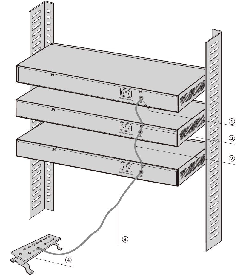
· The signal lightning arrester should be installed close to the protected device, and a short ground wire should be used to connect the lightning arrester to the device’s protective ground. The general installation of the signal lightning arrester is shown in the figure below:
① Grounding Terminal ② Equipotential Bonding Cable ③ Ethernet Cable ④ Signal Lightning Arrester ⑤ Device
|
Note: Signal lightning arrester is not provided with the product. Users need to prepare it by themselves. When using a signal lightning arrester, refer to its user guide and strictly follow the installation requirements. |
|---|
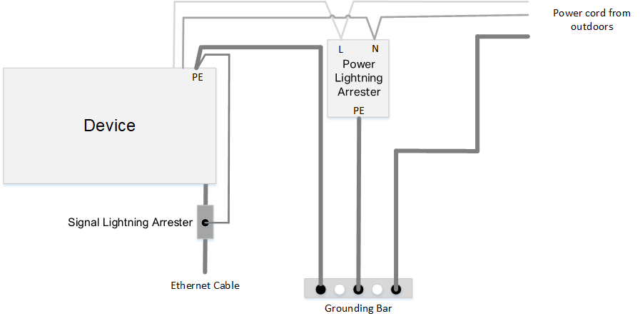
6.3 Installation Example (Lightning Arrester)
The following figure illustrates how to correctly install a lightning arrester: